Textile fabric coating equipment

A technology for textile fabrics and coatings, applied in the field of textile fabrics, can solve the problems of color confusion on the upper surface of textile fabrics and increase in reject rate, and achieve the effect of avoiding color confusion and reducing reject rate.

Inactive Publication Date: 2021-06-04
上海鹏双商贸有限公司
View PDF0 Cites 0 Cited by
  • Summary
  • Abstract
  • Description
  • Claims
  • Application Information

AI Technical Summary

Problems solved by technology

[0002] Textile fabrics refer to weaving fibers into dense nets through weaving, which can be used to make clothes, etc. Textile fabrics with different properties can be obtained through different fibers and weaving methods. Sometimes in order to enhance a certain performance of textile fabrics or require To add color to the surface of textile fabrics, it is necessary to coat the textile fabrics through coating equipment. Adding cadmium red powder to water and adding a thickener can obtain viscous red coating raw materials. It is often used in coloring. After use, it is necessary to blow hot air into the coating equipment for drying, so that it can be quickly dried and condensed on the surface of the textile fabric to avoid sticking around during transportation. However, when the coating equipment is in the air When the workshop of the cadmium sulfide powder particles contained in the coating is coated, in the process of blowing hot air for drying, it is easy to suck the cadmium sulfide powder particles into the cadmium red colloid at the same time, and then blow them into the cadmium red colloid, and produce with cadmium red The reaction produces orange color, which makes the color of the upper surface of the output textile fabric confused, resulting in an increase in the reject rate

Method used


Image

  • Textile fabric coating equipment
  • Textile fabric coating equipment
  • Textile fabric coating equipment

Examples


Embodiment 1

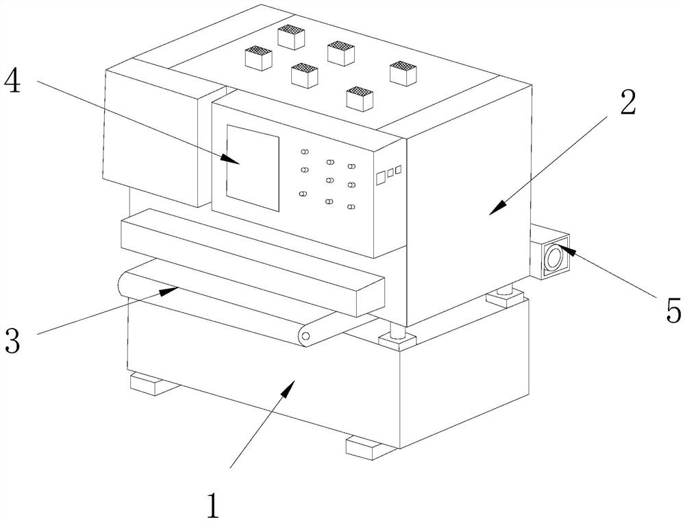
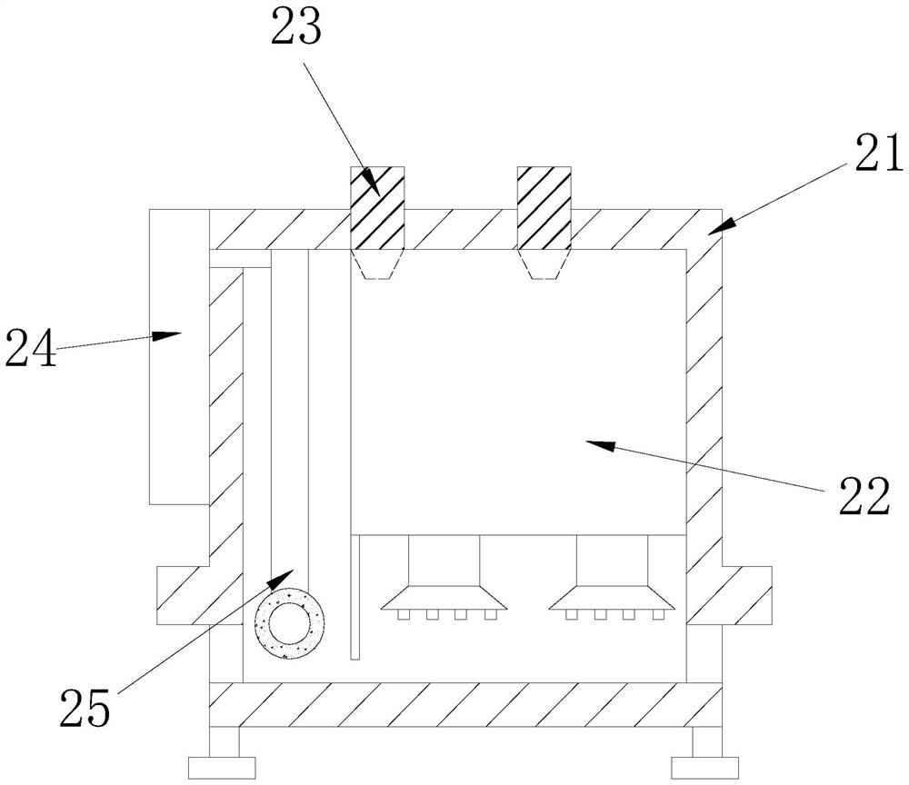
[0026] see Figure 1-Figure 5 , the specific embodiment of the present invention is as follows: a kind of textile fabric coating equipment, its structure comprises base 1, coating machine 2, feeding belt 3, console 4, power machine 5, described base 1 top surface and coating machine 2 bottom surfaces Welding connection, the back of the console 4 is embedded in the front of the coating machine 2, the right side of the feeding belt 3 is nested and connected to the left side of the power machine 5, and the front side of the power machine 5 is welded to the back of the coating machine 2; The layer machine 2 includes a shell 21, a hot air machine 22, an air extraction pipe 23, a paint box 24, and a smearing rod 25. The inside of the shell 21 is welded to the outer layer of the air heat machine 22, and the bottom of the air extraction pipe 23 is embedded in the heat air machine 22. The right side of the paint box 24 and the left side of the smear rod 25 are connected to each other a...

Embodiment 2

[0032] see Figure 6-Figure 8The specific embodiments of the present invention are as follows: the air guide plate A25 includes a plate body B1, a chuck B2, a backflow tank B3, and a blocking bar B4, the top surface of the board body B1 is embedded and connected to the bottom surface of the chuck B2, and the backflow The groove B3 and the left side of the plate body B1 are integrally formed, and the bottom of the blocking bar B4 is engaged with the inner layer of the backflow groove B3. There are multiple backflow grooves B3, and the gaps between the multiple backflow grooves B3 are evenly distributed on the plate. The left side of body B1 is conducive to increasing the number of backflows and making the filtering effect better.

[0033] Wherein, the blocking bar B4 includes a card wheel B41, a connecting bar B42, a bearing bar B43, a contact groove B44, and a sticky head B45. B44 and the outer layer of the bearing rod B43 are integrally formed, the bottom of the sticky head ...


PUM


Abstract

The invention discloses textile fabric coating equipment. The textile fabric coating equipment structurally comprises a base, a coating machine, a feeding belt, a control table and a power machine; the top face of the base is connected with the bottom face of the coating machine in a welded mode; and the back face of the control table is fixedly embedded in the front face of the coating machine. According to the textile fabric coating equipment, outside air is extracted through an air extraction pipe; in the extraction process, large particles in air flow are filtered through a filter cover; a filter wheel is pushed to rotate through the pressure of the air flow, the filter wheel is in contact with a contact handle in the pushing process and is guided on the contact handle; and cadmium sulfide powder contained in the air is stuck and stored after the filter wheel is in contact with multiple blocking rods in the guiding process; after the preliminarily filtered air is subjected to adsorption filtration on floccule and metal particles through adsorption, clean air is input into a heat engine to be heated and sprayed to the surface of the textile fabric to dry cadmium red, so that the situation that the color of the upper layer of the textile fabric is disordered due to the existence of cadmium sulfide powder in the air is effectively avoided; and the occurrence probability of rejects is reduced.

Description

technical field [0001] The invention relates to the field of textile fabrics, in particular to a textile fabric coating equipment. Background technique [0002] Textile fabrics refer to weaving fibers into dense nets through weaving, which can be used to make clothes, etc. Textile fabrics with different properties can be obtained through different fibers and weaving methods. Sometimes in order to enhance a certain performance of textile fabrics or require To add color to the surface of textile fabrics, it is necessary to coat the textile fabrics through coating equipment. Adding cadmium red powder to water and adding a thickener can obtain viscous red coating raw materials. It is often used in coloring. After use, it is necessary to blow hot air into the coating equipment for drying, so that it can be dried quickly and condensed on the surface of the textile fabric to avoid sticking around during transportation. However, when the coating equipment is in the air When coating...

Claims


Application Information

Patent Timeline
IPC IPC(8): B05D3/04B01D50/00
CPCB01D50/00B05D3/0413
Inventor 张鹏
Owner 上海鹏双商贸有限公司
Why Eureka
Try Eureka