Drainage device for cardiovascular medicine department
A cardiovascular and internal medicine technology, applied in the field of drainage for cardiovascular medicine, which can solve the problems of insignificant drainage effect, increased drainage difficulty, and increased patient suffering.
- Summary
- Abstract
- Description
- Claims
- Application Information
AI Technical Summary
Problems solved by technology
Method used
Image
Examples
Embodiment 1
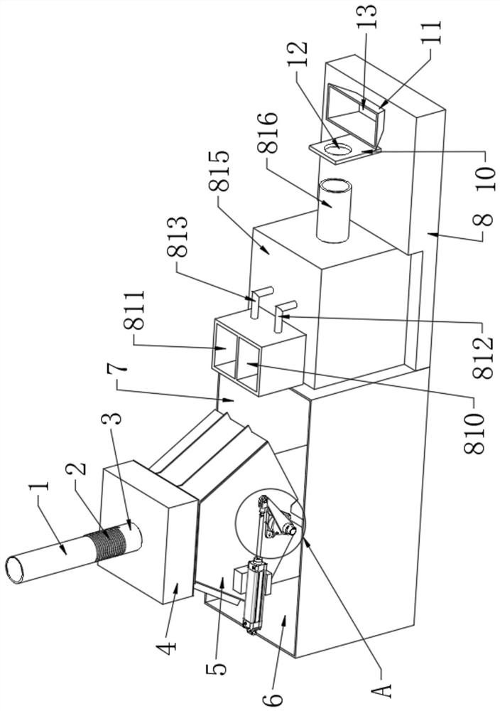
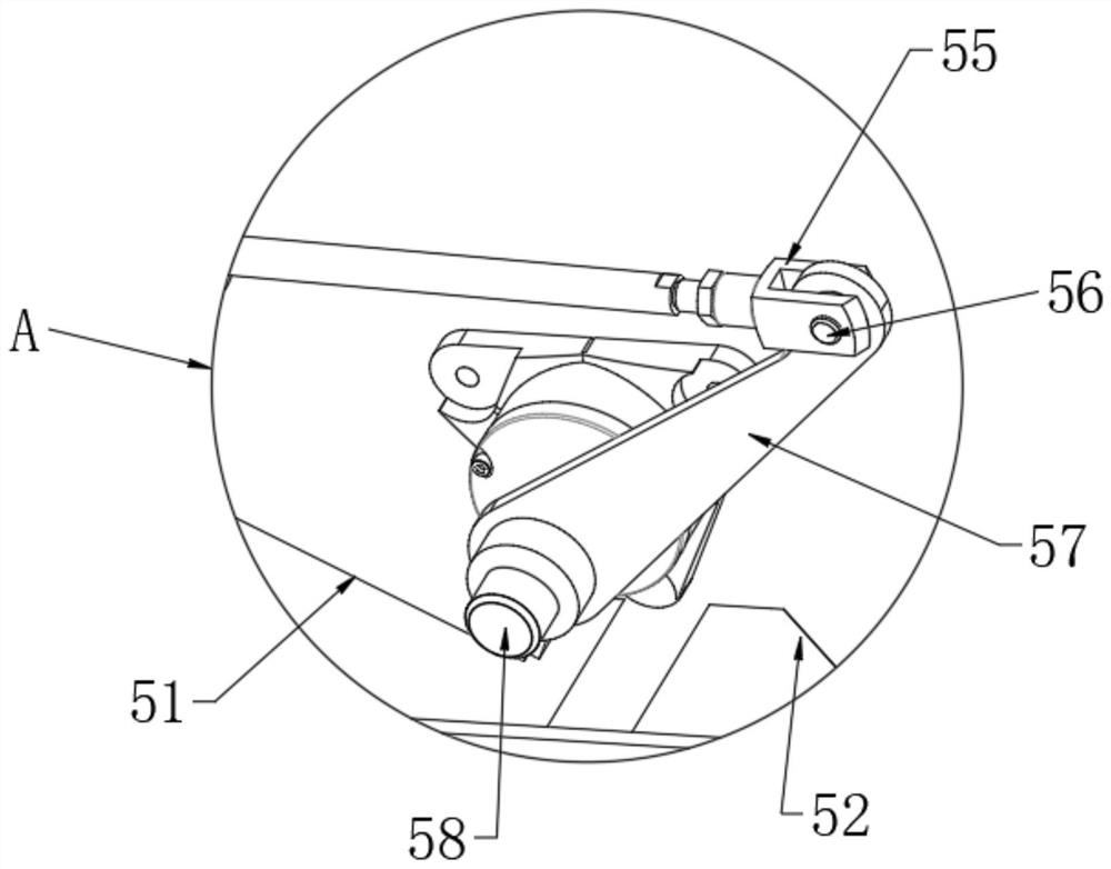
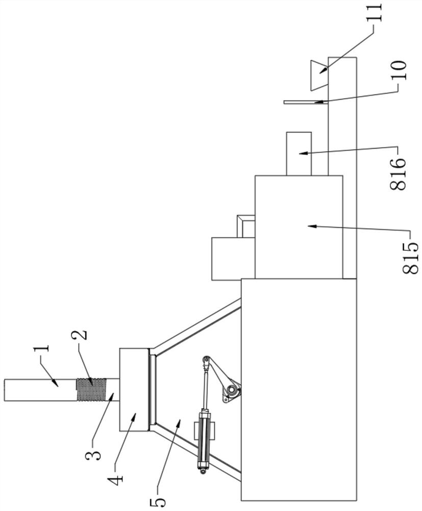
[0052] Such as Figure 1-8 As shown, a drainage device for cardiovascular medicine according to an embodiment of the present invention is composed of a negative pressure drainage device 4, a shunt 5, a first liquid storage tank 6, a second liquid storage tank 7, a cleaning mechanism 8 and a waste liquid collection unit. Box of 9 compositions.
[0053] Among them, the drainage equipment currently used generally only adopts a simple gravity drainage method, and the drainage effect is not obvious. In order to prevent the reflux phenomenon during the drainage process, a negative pressure drainage device 4 is provided. A joint 3 is threadedly connected. Since the angle of drainage is often adjusted according to needs when performing drainage treatment on a patient, the upper end of the joint 3 is fixedly connected with a bellows 2, and the upper end of the bellows 2 is fixedly connected with a drainage tube 1, which can pass through the corrugated Tube 2 adjusts drainage tube 1 to...
Embodiment 2
[0063] On the basis of Example 1, please refer to figure 1 , image 3 with Figure 4 , since the bellows 2 will be bent during the treatment of patients, in order to make the cleaning process effective, a correction tube 816 is fixedly connected to the right side wall of the dust cover 815, and the inner diameter of the correction tube 816 is the same as the outer diameter of the bellows 2. The diameters are consistent, and the outer diameter of the fixed pipe 87 is smaller than the inner diameter of the joint 3.
[0064] By adopting the above technical solution, the joint 3 and the corrugated tube 2 are passed through the straightening tube 816 , and the corrugated tube 2 is straightened by the extrusion of the straightening tube 816 , and the fixing tube 87 is located in the lumen of the joint 3 .
Embodiment 3
[0066] On the basis of Example 1, please refer to Figure 6-8 , the fixed pipe 87 includes a third annular pipe 871, the left side wall of the third annular pipe 871 is provided with a card slot 873, the right end of the third annular pipe 871 is provided with a connecting pipe 874, and the right end of the connecting pipe 874 is provided with a The fourth annular tube 872 , the third annular tube 871 , the connecting tube 874 and the fourth annular tube 872 are integrally formed.
[0067] By adopting the above-mentioned technical solution, the third annular tube 871 and the fourth annular tube 872 play a role in supporting the fastening mechanism 88. Since the moving tube 86 contacts the fixed tube 87, the moving tube 86 will press against the fixed tube 87. Due to impact force, the left end of the fixed pipe 87 is prone to deformation after long-term use, so a rubber gasket is provided in the slot 873 .
PUM
 Abstract
Description
Claims
Application Information
 - R&D
- Intellectual Property
- Life Sciences
- Materials
- Tech Scout
- Unparalleled Data Quality
- Higher Quality Content
- 60% Fewer Hallucinations
Browse by: Latest US Patents, China's latest patents, Technical Efficacy Thesaurus, Application Domain, Technology Topic, Popular Technical Reports.
© 2025 PatSnap. All rights reserved.Legal|Privacy policy|Modern Slavery Act Transparency Statement|Sitemap|About US| Contact US: help@patsnap.com


