
Drawer button positioning device for low-voltage switch cabinet

A low-voltage switchgear and positioning device technology, which is applied to switchgear, switchgear parts, pull-out switchgear, etc., can solve the problems of button damage, circumferential rotation, and need for repair, so as to prolong the service life and facilitate adjustment , to avoid the effect of wear and damage

Inactive Publication Date: 2021-06-01
范华飞
View PDF1 Cites 0 Cited by
  • Summary
  • Abstract
  • Description
  • Claims
  • Application Information

AI Technical Summary

Problems solved by technology

[0007] In order to solve the above technical problems, the present invention provides a drawer button positioning device for low-voltage switchgear to solve the problem that the existing drawer positioning mechanism is relatively complicated, takes up a large space, and has high cost during installation and replacement. There will be a phenomenon of circumferential rotation, which will affect the service life of the button. When the switch button is pressed, it is easy to dislocate and collapse, and it is easy to damage the button, resulting in the need for repairs, wasting manpower and material resources, and affecting the normal operation of the circuit. After using it for a period of time, the pressing place is dirty, and it takes a lot of effort to clean it, and it is also a problem that it takes a lot of effort to install and replace the button.

Method used


Image

  • Drawer button positioning device for low-voltage switch cabinet
  • Drawer button positioning device for low-voltage switch cabinet
  • Drawer button positioning device for low-voltage switch cabinet

Examples


Embodiment

[0037] as attached figure 1 To attach Figure 10 Shown:

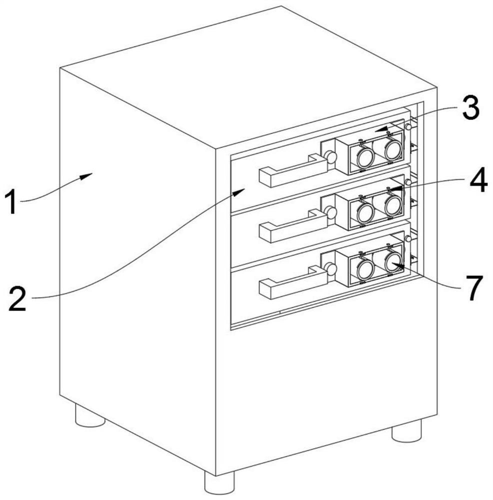
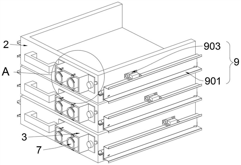
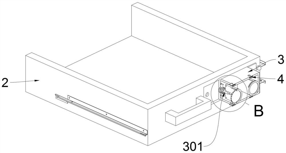
[0038]The invention provides a drawer button positioning device for a low-voltage switch cabinet, which includes a box body 1; Set the positioning mechanism 9, and a handle is installed on the drawer 2; a rectangular slot is provided on the drawer 2, and a connecting shell 3 is fixed in the rectangular slot by bolts. When in use, the rectangular slot facilitates the installation of the connecting shell 3, and the rectangular slot The supporting force of the connecting shell 3 is also increased; two stoppers 4 and limit bolts 5 are symmetrically installed on the connecting shell 3, and two slidingly connected buttons 6 are installed on the connecting shell 3; The friction block 7 and the button 6 are symmetrically equipped with two waist-shaped rubber pads 8 .

[0039] Wherein, one side of the button 6 is provided with a circular installation groove, and the installation groove fits with the friction block 7, and the ...


PUM


Abstract

The invention provides a drawer button positioning device for a low-voltage switch cabinet, and belongs to the technical field of low-voltage switches. The device comprises a box body; a group of drawers are mounted on the box body, and a group of supporting seats are mounted at the bottom of the box body; a group of positioning mechanisms are arranged between the box body and the drawer, and a handle is arranged on each drawer; a rectangular groove is formed in each drawer, and a connecting shell is fixed in each rectangular groove through a bolt; and two stop blocks and limiting bolts are symmetrically mounted on a connecting shell. A limiting bolt is arranged on the connecting shell, a kidney-shaped sliding groove is formed in the button, the button is convenient to install and replace due to the arrangement of the limiting bolt, a check block is arranged on the connecting shell, the check block has the anti-loosening and dustproof effects of the limiting bolt, a friction block is arranged on the button, and when the friction block is seriously abraded or dust adheres to the friction block, the friction block slides upwards to be taken out and replaced, and abrasion and damage caused by directly pressing the button are avoided through the arrangement of the friction block.

Description

technical field [0001] The invention belongs to the technical field of low-voltage switches, and more specifically relates to a positioning device for a drawer button of a low-voltage switch cabinet. Background technique [0002] Low-voltage switches are roughly classified into three categories: automotive low-voltage protection switches, pressure-controlled low-voltage switches, and low-voltage switching appliances for power equipment. It is suitable for the automobile industry, water purifier industry, electric power industry and other fields. There will be multiple drawers on the low-voltage switch cabinet, and there will be buttons on the drawers. When the drawers and buttons are installed, there will be installation errors. A kind of drawer is needed. The positioning device of the button solves the problem of wrong installation. [0003] For example, the application number: CN201310119037.1 Chinese invention patent, which discloses a drawer position device for low-volt...

Claims


Application Information

Patent Timeline
IPC IPC(8): H02B11/10H02B11/173
CPCH02B11/10H02B11/173
Inventor 范华飞
Owner 范华飞
Learn More