
Transformer bushing

A transformer bushing and coiling technology, which is applied to transformer/inductance parts, circuits, electrical components, etc., can solve the problem of increased inner diameter of conductive rods, small current-carrying guide rods that cannot match the winding shaft, and inconvenient production and use. and other issues to achieve the effect of ensuring reliability

Pending Publication Date: 2021-06-01
JIANGSU SHENMA ELECTRIC CO LTD
View PDF0 Cites 1 Cited by
  • Summary
  • Abstract
  • Description
  • Claims
  • Application Information

AI Technical Summary

Problems solved by technology

[0002] The power transformer is one of the most important and expensive key power equipment in the power system, and the transformer bushing is one of the key components of the transformer. , due to the larger diameter of the lead wire, the inner diameter of the conductive rod of the transformer bushing will increase accordingly, and the diameter of the aluminum tube of the coiled capacitor core will also increase, so it is not convenient for production and use
[0003] In addition, for high-current transformer bushings, the guide rod structure is generally adopted, and the capacitor core is directly wound on the current-carrying guide rod, and the capacitor core of the whole roll needs to be in the middle of the winding tube when winding Insert the winding shaft, and the inner diameter of the current-carrying guide rod is generally too small to match the winding shaft, and the thinner winding shaft will easily cause the winding shaft to rotate during the winding process

Method used


Image

  • Transformer bushing
  • Transformer bushing
  • Transformer bushing

Examples


Embodiment Construction

[0029] As required, specific embodiments of the invention will be disclosed herein. However, it should be understood that the embodiments disclosed herein are merely typical examples of the invention, which can be embodied in various forms. Therefore, specific details disclosed herein are not to be considered limiting, but merely as a basis for the claims and as a representative basis for teaching one skilled in the art to variously employ the invention in any appropriate way in practice, This includes taking various features disclosed herein and combining features that may not be expressly disclosed herein.

[0030] The "connection" mentioned in the present invention should be interpreted in a broad sense unless otherwise specified or limited, and may be a direct connection or a connection through an intermediary. In the description of the present invention, it should be understood that the orientation or positional relationship indicated by "upper", "lower", "end", "one end...


PUM


Abstract

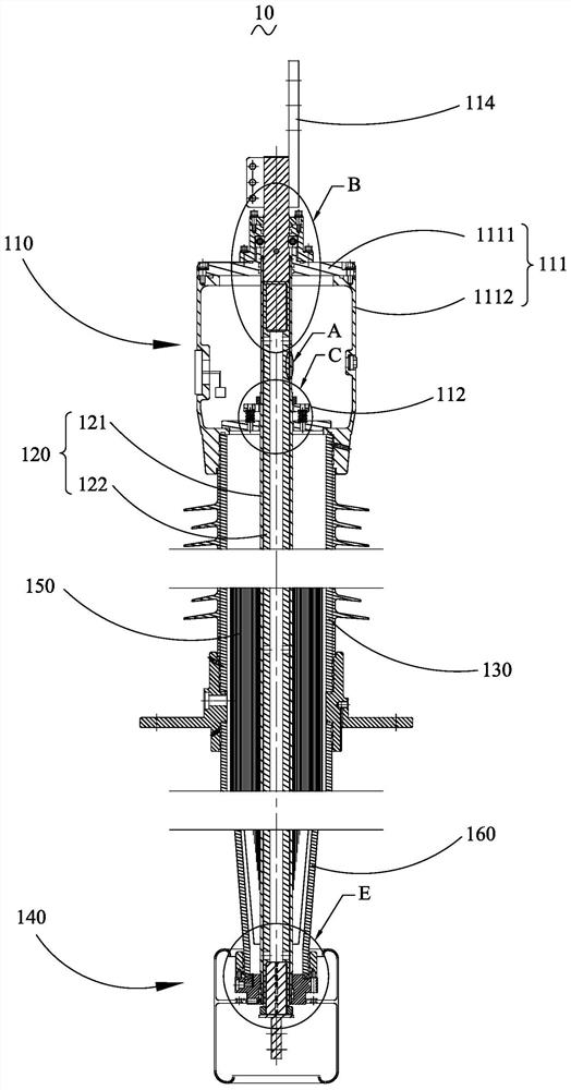
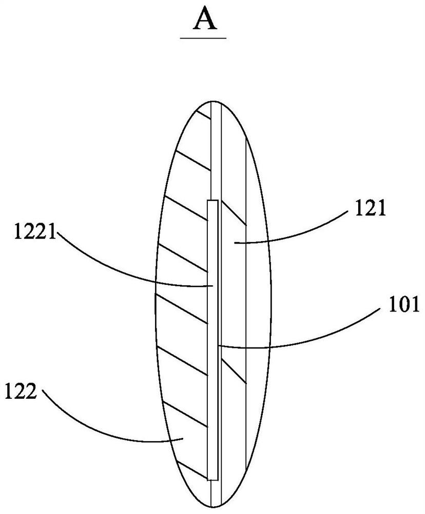
The invention discloses a transformer bushing, which comprises a head assembly, a central conduit, a composite jacket and a tail assembly, the central conduit sequentially penetrates through the head assembly, the composite jacket and the tail assembly, the central conduit comprises a current-carrying rod and a winding pipe, the current-carrying rod comprises a first guide rod and a second guide rod, and the first guide rod and the second guide rod are fixedly connected, the winding pipe is sleeved outside the current-carrying rod, a gap between the winding pipe and the current-carrying rod is not less than 3mm, and the length of the winding pipe is less than that of the current-carrying rod. The transformer bushing is simple in structure, reliable winding of a capacitor core and reliable current carrying of the conducting rod can be guaranteed, meanwhile, stable connection and reliable matching between parts are guaranteed, exchange of transformer bushing products of the same voltage class can be achieved, and universality is achieved.

Description

technical field [0001] The invention relates to the technical field of power transmission and transformation insulation equipment, in particular to a transformer bushing. Background technique [0002] The power transformer is one of the most important and expensive key power equipment in the power system, and the transformer bushing is one of the key components of the transformer. , due to the large diameter of the lead-out wire, the inner diameter of the conductive rod of the transformer bushing will increase accordingly, and the diameter of the aluminum tube of the coiled capacitor core will also increase, so it is not easy to produce and use. [0003] In addition, for high-current transformer bushings, the guide rod structure is generally adopted, and the capacitor core is directly wound on the current-carrying guide rod, and the capacitor core of the whole roll needs to be in the middle of the winding tube when winding Insert the winding shaft, and the inner diameter of...

Claims


Application Information

Patent Timeline
Patent Type & Authority Applications(China)
IPC IPC(8): H01F27/04H01B17/28
CPCH01F27/04H01B17/28
Inventor 孙中源孙略高俊
Owner JIANGSU SHENMA ELECTRIC CO LTD
Learn More