
Sewage treatment device

A technology of sewage treatment device and stirring device, which is applied in biological water/sewage treatment, water/sludge/sewage treatment, special treatment targets, etc., to achieve good crushing effect, improve sewage treatment effect, and increase the effect of decontamination effect.

Pending Publication Date: 2021-06-01
林臣鑫
View PDF6 Cites 0 Cited by
  • Summary
  • Abstract
  • Description
  • Claims
  • Application Information

AI Technical Summary

Problems solved by technology

[0005] Aiming at the deficiencies of the prior art, the present invention provides a sewage treatment device, which solves the problem of biological treatment of large particle pollutants in sewage

Method used


Image

  • Sewage treatment device
  • Sewage treatment device
  • Sewage treatment device

Examples


Embodiment 1

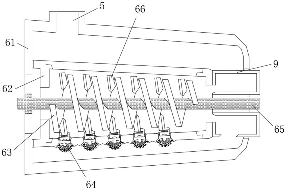
[0033] Such as Figure 1-4As shown, the present invention provides a technical solution: a sewage treatment device, including a treatment machine tool 1 and a stirring device 6, the bottom of the treatment machine tool 1 is fixedly connected with a support foot 2, and the left side of the upper surface of the treatment machine tool 1 is Fixedly connected with a fixed block 3, the middle position of the fixed block 3 is provided with a sewage inlet 4, the right side of the upper surface of the processing machine tool 1 is fixedly connected with a rotating motor 8, and the stirring device 6 is arranged on the fixed block 3 and Between the opposite faces of the rotating motor 8, and the stirring device 6 communicates with the sewage inlet 4, the stirring device 6 is movably connected with the rotating motor 8, and the outer surface of the left side of the stirring device 6 is provided with a first water outlet 5 , the right side of the stirring device 6 is fixedly connected with ...

Embodiment 2

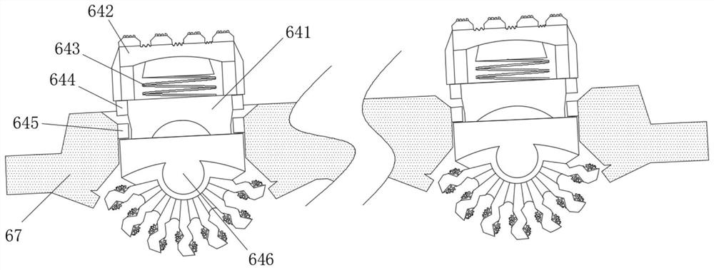
[0040] Such as Figure 5-6 As shown, on the basis of Embodiment 1, the present invention provides a technical solution: the biological decontamination device 646 includes a decontamination block 6461, and the top of the decontamination block 6461 is fixedly connected to the bottom of the device block 641, so Both sides of the bottom of the decontamination block 6461 are fixedly connected with a second spring 6462 , and the bottom of the second spring 6462 is fixedly connected with a pressing plate 6463 . The biological decontamination device 646 is pushed downwards to contact the inner wall of the bottom of the stirring outer cylinder 61, and under the action of the second spring 6462 and the pressure plate 6463, the entire biological decontamination device 646 can be integrally attached to the inner wall of the bottom of the stirring outer cylinder 61, so that The biological decontamination device 646 has no dead angle in the filtration area, which increases the decontaminati...


PUM


Abstract

A sewage treatment device comprises a treatment machine tool and a stirring device, supporting legs are fixedly connected to the bottom of the treatment machine tool, a fixing block is fixedly connected to the left side of the upper surface of the treatment machine tool, a sewage inlet is formed in the middle of the fixing block, and a rotating motor is fixedly connected to the right side of the upper surface of the treatment machine tool; and the stirring device is arranged between the opposite faces of the fixed block and the rotating motor, the stirring device communicates with the sewage inlet and is movably connected with the rotating motor, a first water outlet is formed in the outer surface of the left side of the stirring device, a second water outlet is fixedly connected to the right side of the stirring device, and the stirring device comprises a stirring outer cylinder. The invention relates to the technical field of sewage treatment. According to the sewage treatment device, sewage enters the outer stirring cylinder from the sewage inlet, and the inner cylinder is arranged at the eccentric shaft of the outer stirring cylinder, so that the treatment effect of the sewage at the bottom is better.

Description

technical field [0001] The invention relates to the technical field of sewage treatment, in particular to a sewage treatment device. Background technique [0002] The biological method of sewage treatment is to use the metabolic function of microorganisms to degrade the dissolved and colloidal organic pollutants in the sewage and convert them into harmless substances, so that the sewage can be purified. Judging from the research and application status and development of wastewater biological treatment at home and abroad, various new wastewater biological treatment processes are continuously introduced, and the efficiency of wastewater treatment is getting higher and higher. In the future, wastewater treatment will be advanced, efficient, energy-saving, and more automated. direction of development. [0003] For an existing sewage treatment device, because sewage often contains large-particle pollutants, under the action of biological treatment, microorganisms often cannot pe...

Claims


Application Information

Patent Timeline
IPC IPC(8): C02F3/00C02F3/34
CPCC02F3/00C02F3/34C02F2303/26C02F2303/14
Inventor 林臣鑫
Owner 林臣鑫
Learn More