One-inch photo pressing and cutting type separation equipment
A kind of separation equipment and symmetrical technology, applied in metal processing and other directions, can solve the problems of automatic fixation, waste flying to the ground, and different sizes of press-cut photos, etc., and achieve the effect of size standard
- Summary
- Abstract
- Description
- Claims
- Application Information
AI Technical Summary
Problems solved by technology
Method used
Image


Examples
Embodiment 1
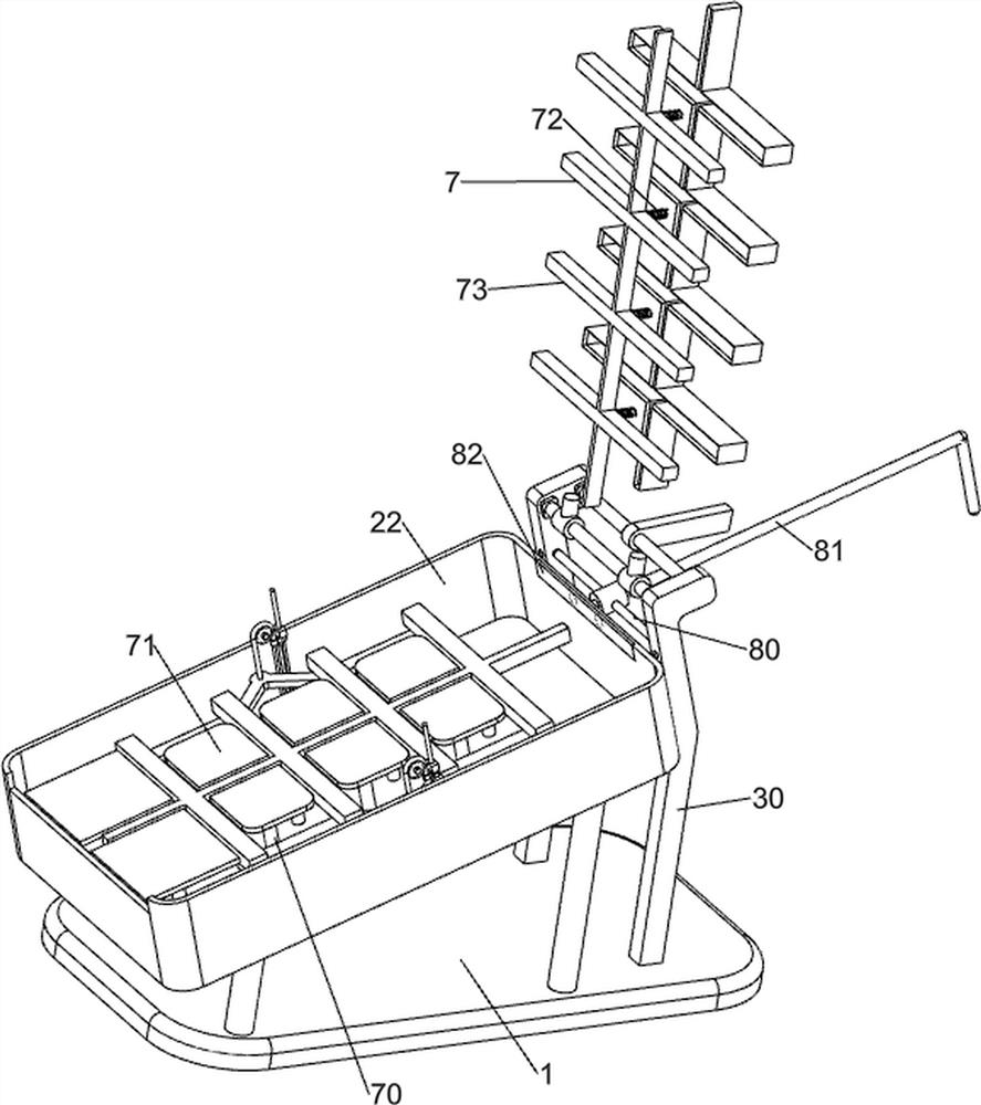
[0031] A one-inch photo-press-cutting separation equipment, such as figure 1 , figure 2 with image 3 As shown, it includes a base 1, a placing mechanism 2 and a pressing and cutting mechanism 3. The placing mechanism 2 is provided on the top of the base 1, and the pressing and cutting mechanism 3 is provided on the right side of the base 1. The pressing and cutting mechanism 3 is located above the placing mechanism 2, and the placing mechanism 2 Cooperate with press-cut mechanism 3 to work.
[0032] When people need to press, cut and separate the photos, they manually put the photos into the 2 parts of the placement mechanism, and then manually run the 3 parts of the pressing and cutting mechanism to press and cut the photos. After the pressing and cutting are completed, people manually collect them. After the photo pressing and cutting is completed, people manually lift the three parts of the pressing and cutting mechanism to sort out the waste materials of the equipment....
Embodiment 2
[0034] On the basis of Example 1, such as figure 1 , figure 2 with image 3 As shown, the placement mechanism 2 includes a long pillar 20, a short pillar 21, a support frame 22 and a placement frame 23, the long pillar 20 is arranged symmetrically on the right side of the top of the base 1, and the short pillar is arranged symmetrically on the left side of the top of the base 1 21. A supporting frame 22 is provided between the tops of the long pillar 20 and the short pillar 21, the supporting frame 22 is inclined at a certain angle, and the upper part of the supporting frame 22 is provided with a placing frame 23.
[0035] When people need to press and cut photos, people place the photos on the rack 23, and people manually run the pressing and cutting mechanism 3 to press and cut the photos. Fall into the support frame 22, just sort out and remove the waste in the equipment.
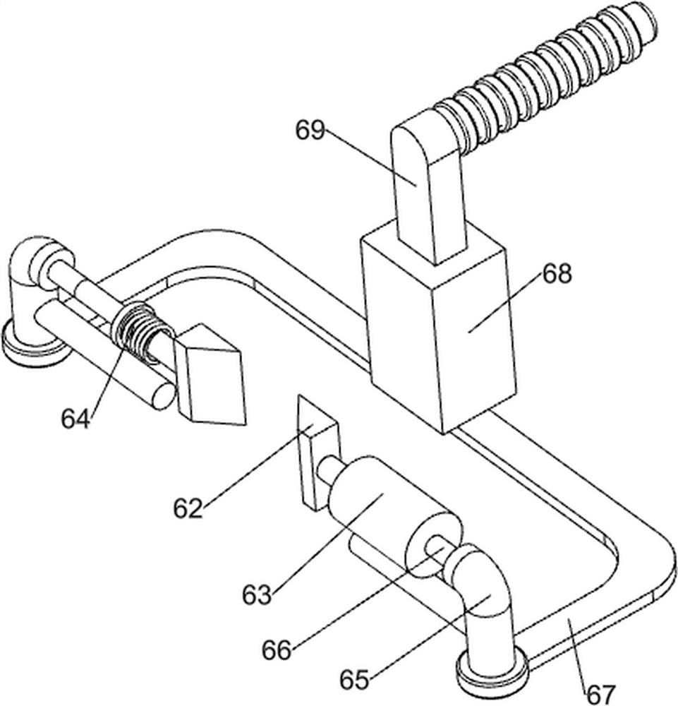
[0036]Pressing and cutting mechanism 3 includes support plate 30, rotating shaft 31, installation...
Embodiment 3
[0039] On the basis of Example 2, such as Figure 4 , Figure 5 , Image 6 , Figure 7 , Figure 8 , Figure 9 , Figure 10 with Figure 11 As shown, the rising assembly 4 includes a sliding cylinder 40, a sliding shaft 41, a tension spring 42, a special-shaped frame 43, a connecting rod 44, a reel 45, a slide rail 46, a slide block 47, a stay cord 48, a block 49, Compression rod 410 and pressure block 411, the inside of the support frame 22 is evenly provided with sliding cylinders 40 in the middle left and right, the number of sliding cylinders 40 is 4, sliding shafts 41 are provided in the sliding cylinders 40, and tension springs 42 are provided at the bottom of the sliding shafts 41 , the sliding shaft 41 is connected to the inside of the support frame 22 through a tension spring 42, a special-shaped frame 43 is arranged between the top of the sliding shaft 41, and connecting rods 44 are provided on the front and rear sides of the bottom of the special-shaped frame ...
PUM
 Abstract
Description
Claims
Application Information
 - R&D
- Intellectual Property
- Life Sciences
- Materials
- Tech Scout
- Unparalleled Data Quality
- Higher Quality Content
- 60% Fewer Hallucinations
Browse by: Latest US Patents, China's latest patents, Technical Efficacy Thesaurus, Application Domain, Technology Topic, Popular Technical Reports.
© 2025 PatSnap. All rights reserved.Legal|Privacy policy|Modern Slavery Act Transparency Statement|Sitemap|About US| Contact US: help@patsnap.com