
Tin soldering workbench capable of improving tin soldering efficiency

A workbench and soldering technology, applied in the field of desks, can solve the problems of user body loss, low adjustment efficiency, inability to adjust arbitrarily, etc., and achieve the effects of increasing stability, convenient height adjustment, and avoiding body loss.

Active Publication Date: 2021-06-01
湖北卓茂智能科技有限公司
View PDF4 Cites 1 Cited by
  • Summary
  • Abstract
  • Description
  • Claims
  • Application Information

AI Technical Summary

Problems solved by technology

[0002] Desks generally appear in people's work, study and life. A good desk can not only improve the comfort of the human body but also improve the work efficiency of people. When soldering, users need to raise their body height to facilitate soldering. When soldering, you need to lower your posture to observe the effect of soldering. Therefore, the upper body of the user is constantly changing compared with the desk. The existing desks not only need to use tools such as screwdrivers when adjusting the height, some also need more tools. Height adjustment with personal cooperation leads to low adjustment efficiency and cannot be adjusted arbitrarily, which leads to the user's need for height change when soldering is all realized through the movement of the upper body, which will cause wear and tear on the user's body for a long time

Method used


Image

  • Tin soldering workbench capable of improving tin soldering efficiency
  • Tin soldering workbench capable of improving tin soldering efficiency
  • Tin soldering workbench capable of improving tin soldering efficiency

Examples


Embodiment Construction

[0032]The following will clearly and completely describe the technical solutions in the embodiments of the present invention with reference to the accompanying drawings in the embodiments of the present invention. Obviously, the described embodiments are only some, not all, embodiments of the present invention. Based on the embodiments of the present invention, all other embodiments obtained by persons of ordinary skill in the art without making creative efforts belong to the protection scope of the present invention.

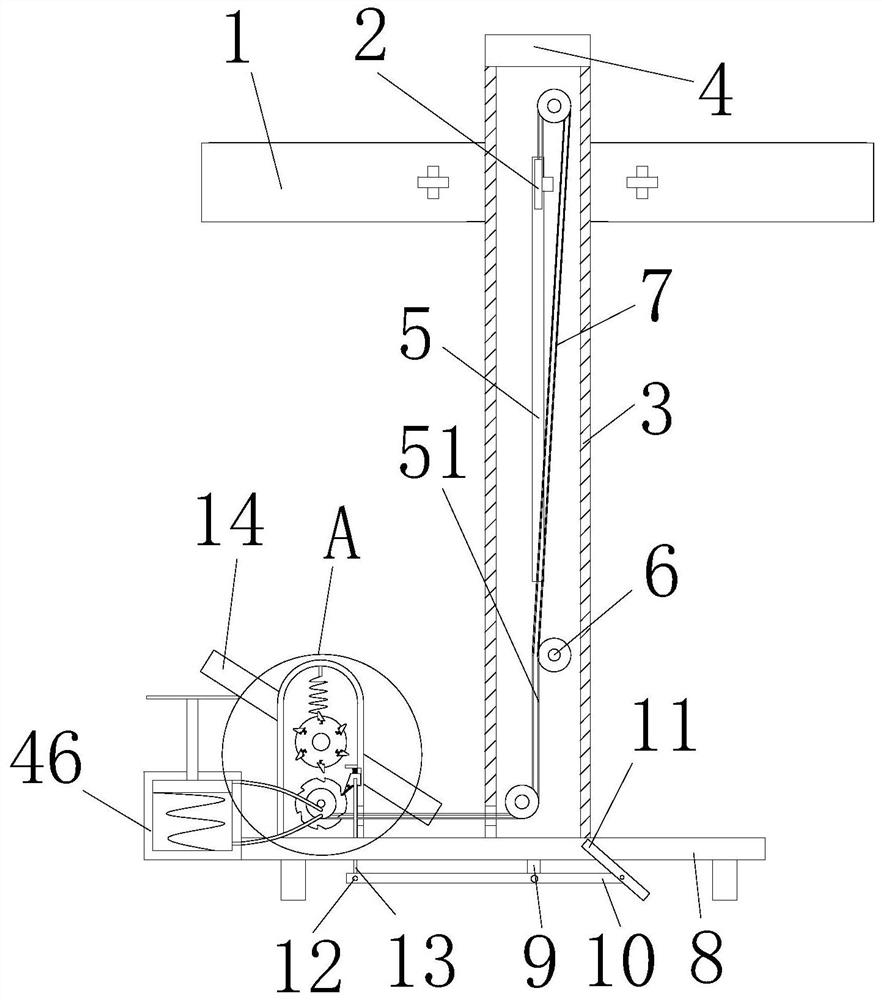
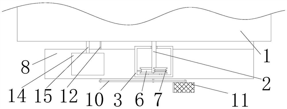
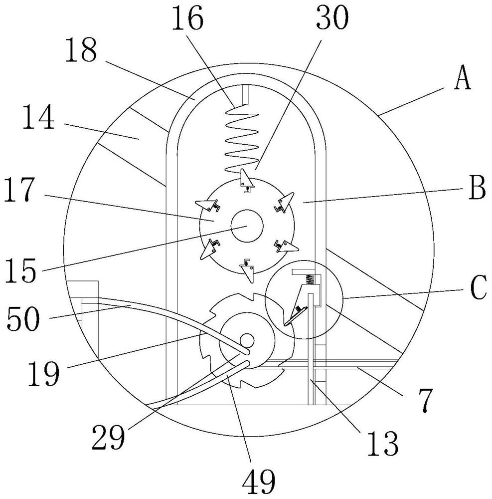
[0033] see Figure 1-8 , a soldering workbench for improving soldering efficiency, comprising a table board 1, a support frame 3, a pulley block 6, a steel wire rope 7, an underframe 8, an auxiliary pedal 11 and a main pedal 14, the support frame 3 has a rectangular structure, and the support frame The interior of 3 is hollowed out and the top surface is open. The back of the support frame 3 is provided with a lifting hole 5. The internal movement of the liftin...


PUM


Abstract

The invention relates to the technical field of tables, and discloses a tin soldering workbench capable of improving the tin soldering efficiency. The tin soldering workbench comprises a table board, a support frame, pulley blocks, a steel wire rope, a bottom frame, an auxiliary pedal and a main pedal, the rear inner wall of the support frame is provided with the three pulley blocks, the three pulley blocks are connected through the steel wire rope, the bottom surface of the support frame is fixedly connected with the bottom frame, a transmission box body is fixedly installed on the top face of the bottom frame, a movable hole is formed in the back face of the transmission box body, the front inner wall of the transmission box body is connected with a transmission wheel through a rotating shaft, the front face of the transmission wheel is fixedly connected with a wire coil, the outer wall of a connecting shaft is movably connected with a connecting rod in a sleeved mode, a fixing block is fixedly connected to the bottom face of the bottom frame, the fixing block is located at the front end of the bottom frame, the connecting rod is connected to the fixing block by means of a rotating shaft, the right end of the connecting rod is connected with the auxiliary pedal through a rotating shaft, the auxiliary pedal is located in front of the bottom frame, all structures arranged on the front face of the table board and the front face of the main pedal are arranged on the back faces of the table board and the main pedal in a mirroring mode, the structure is reasonable, and the height is convenient to adjust.

Description

technical field [0001] The invention relates to the technical field of desks, in particular to a soldering workbench for improving soldering efficiency. Background technique [0002] Desks generally appear in people's work, study and life. A good desk can not only improve the comfort of the human body but also improve the work efficiency of people. When soldering, users need to raise their body height to facilitate soldering. When soldering, you need to lower your posture to observe the effect of soldering. Therefore, the upper body of the user is constantly changing compared with the desk. The existing desks not only need to use tools such as screwdrivers when adjusting the height, some also need more tools. Height adjustment with personal cooperation leads to low adjustment efficiency and inability to adjust arbitrarily. As a result, the user's needs for height changes when soldering are all realized through the movement of the upper body, which will cause wear and tear on...

Claims


Application Information

Patent Timeline
IPC IPC(8): B23K3/00B23K3/06B23K3/08
CPCB23K3/00B23K3/06B23K3/063B23K3/08
Inventor 不公告发明人
Owner 湖北卓茂智能科技有限公司
Learn More