Efficient clothing disinfection equipment for dermatology department
A technology for disinfection equipment and sexually transmitted diseases, which is applied to sanitary equipment, disinfection, water supply devices for toilets, etc., and can solve problems such as poor disinfection effect.
- Summary
- Abstract
- Description
- Claims
- Application Information
AI Technical Summary
Problems solved by technology
Method used
Image
Examples
Embodiment 1
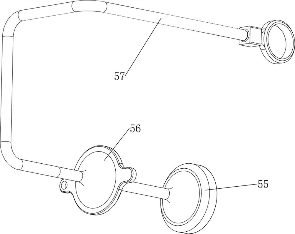
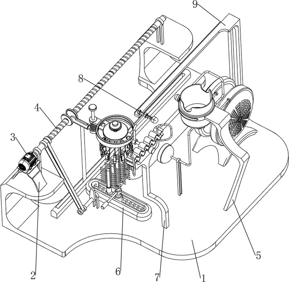
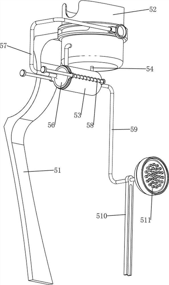
[0029] A kind of high-efficiency clothing disinfection equipment for dermatology and venereal diseases, such as figure 1 As shown, it includes a base plate 1, a support frame 2, a motor 3, a feeding mechanism 4 and a manual spraying mechanism 5, the upper left side of the base plate 1 is provided with a support frame 2, the upper part of the support frame 2 is provided with a motor 3, and the upper left side of the base plate 1 A feeding mechanism 4 is provided, and the feeding mechanism 4 is connected with the motor 3, and the upper right side of the base plate 1 is provided with a manual material spraying mechanism 5.
[0030] When the user needs to sterilize the clothes, this device can be used. First, the clothes to be sterilized are placed in the feeding mechanism 4, and a certain amount of disinfectant is placed in the manual spraying mechanism 5, and then the motor 3 is started, and the motor 3 Drive the feeding mechanism 4 to move, and drive the manual spraying mechani...
Embodiment 2
[0032] On the basis of Example 1, such as Figure 2-4 As shown, the feeding mechanism 4 includes a first fixed column 41, a screw mandrel 42, a nut 43, a first slide rail 44, a first slide bar 45, a second slide bar 46, a fixed plate 47, a turntable 48 and a clamp assembly 49, Base plate 1 upper left side is provided with first fixed column 41 symmetrically front and rear, between the first fixed column 41 on both sides is provided with screw mandrel 42, and screw mandrel 42 is threadedly provided with nut 43, and base plate 1 upper left side A first slide rail 44 is provided, and a first slide bar 45 is slidably provided in the first slide rail 44, and the first slide bar 45 is connected with a nut 43, and the first slide bar 45 top is connected with a second slide bar 46, and the second The upper part of the slide bar 46 is slidably provided with a fixed plate 47 , and the fixed plate 47 is slidably provided with a turntable 48 , and a plurality of clamp assemblies 49 are co...
Embodiment 3
[0037] On the basis of Example 2, such as Figure 5-8 Shown, beating mechanism 6 is also included, and beating mechanism 6 includes the 4th fixed column 61, the first rotating shaft 62, transmission assembly 63, cam 64, push rod 65, the 3rd slide bar 66, the 2nd slide rail 67, the 6th A spring 68 and a beating rod 69, a fourth fixed column 61 is provided on the front side of the upper part of the bottom plate 1, and a first rotating shaft 62 is rotatably arranged on the fourth fixed column 61, and a transmission assembly is connected between the first rotating shaft 62 and the screw rod 42 63, the first rotating shaft 62 is provided with a cam 64, the upper front side of the base plate 1 is provided with a second slide rail 67, and the second slide rail 67 is slidingly provided with a third slide bar 66, and the front side of the third slide bar 66 is connected with Push rod 65, push rod 65 contacts and cooperates with cam 64, and first spring 68 is connected between the left ...
PUM
 Abstract
Description
Claims
Application Information
 - R&D
- Intellectual Property
- Life Sciences
- Materials
- Tech Scout
- Unparalleled Data Quality
- Higher Quality Content
- 60% Fewer Hallucinations
Browse by: Latest US Patents, China's latest patents, Technical Efficacy Thesaurus, Application Domain, Technology Topic, Popular Technical Reports.
© 2025 PatSnap. All rights reserved.Legal|Privacy policy|Modern Slavery Act Transparency Statement|Sitemap|About US| Contact US: help@patsnap.com


