Cab back cover

A cab and vehicle technology, applied in the field of cab rear cover, can solve problems such as thermal damage of components

Pending Publication Date: 2021-05-28
ISUZU MOTORS LTD
View PDF11 Cites 0 Cited by
  • Summary
  • Abstract
  • Description
  • Claims
  • Application Information

AI Technical Summary

Problems solved by technology

At this time, the heated air fills the inside of the cab back, causing problems that may cause thermal damage to the components of the vehicle

Method used


Image

  • Cab back cover
  • Cab back cover
  • Cab back cover

Examples


Embodiment Construction

[0025]

[0026] [Peripheral structure of cab rear cover 7]

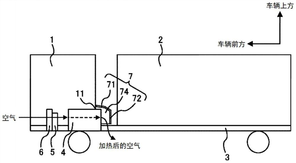
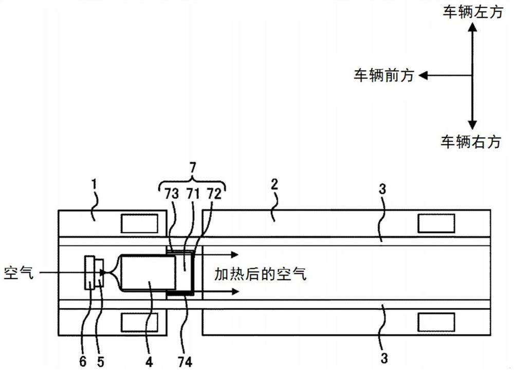
[0027] Figure 1A and Figure 1B It is a figure showing the state of the vehicle provided with the cab rear cover 7 of this embodiment. Figure 1A It is a sectional view of a vehicle provided with the cab rear cover 7 of this embodiment. Figure 1B It is a figure which shows the state of the vehicle which looked at the cab rear cover 7 of this embodiment from below. figure 2 It is a figure which shows the structure of the cab 1 seen from the rear. image 3 It is a figure which shows the state of the vicinity of the cab rear cover 7 in the vehicle provided with the cab rear cover 7 of this embodiment.

[0028] The vehicle is a flat-headed vehicle, such as a truck. The vehicle has a driver's cab 1 , a mounting part 2 , a side frame 3 , an engine 4 , a fan 5 , a radiator 6 and a driver's cab rear cover 7 .

[0029] The cab 1 is, for example, a box-shaped portion provided with a driver's seat, and is provided in f...


PUM


Abstract

A cab back cover is provided behind the cab of the vehicle and has an upper surface portion that prevents air flowing in from the front from flowing out upward, a rear surface portion that prevents air flowing in from the front from flowing out rearward, a left surface portion that prevents air flowing in from the front from flowing out leftward, and a right surface portion that prevents air flowing in from the front from flowing out rightward, wherein at least one of the left surface portion and the right surface portion has a front region extending inward in the vehicle width direction of the vehicle at a first angle with respect to the front-rear direction of the vehicle in a front-to-rear arrangement, and a rear region connected to the rear end of the front region and extending inward in the vehicle width direction of the vehicle at a second angle, which is larger than the first angle, in a front-to-rear arrangement.

Description

technical field [0001] The present disclosure relates to a cab back of a vehicle. Background technique [0002] Conventionally, a cab back is provided in a vehicle. Patent Document 1 discloses an engine cover for a cab-type vehicle. [0003] prior art literature [0004] in the patent literature [0005] Patent Document 1: Japanese Publication No. 62-54853 Contents of the invention [0006] The technical problem to be solved by the invention [0007] In cab-over vehicles, a cab back is sometimes provided on the rear surface of the cab of the vehicle. At this time, the air heated by flowing from the front to the rear around the engine installed below the cab of the vehicle may flow into the inside of the cab back and fill the inside of the cab back. At this time, the heated air fills the inner side of the cab rear cover, causing a problem that thermal damage may occur to components of the vehicle. [0008] Therefore, the present disclosure has been made in view of th...

Claims


Application Information

Patent Timeline
IPC IPC(8): B62D35/00B60K11/04B62D25/08B62D25/20
CPCB62D25/08B60K11/04B62D25/20B62D35/00
Inventor 森直树大福哲史
Owner ISUZU MOTORS LTD
Why Eureka
Try Eureka