
Adjustable 5G antenna mounting base and 5G antenna

An adjustable mounting base technology, applied in the direction of antenna supports/mounting devices, antennas, antenna parts, etc., can solve the problems of non-adjustable directions and angles, achieve simple and convenient rotation, increase friction, and facilitate maintenance and replacement Effect

Pending Publication Date: 2021-05-28
袁佳豪
View PDF0 Cites 1 Cited by
  • Summary
  • Abstract
  • Description
  • Claims
  • Application Information

AI Technical Summary

Problems solved by technology

[0004] The purpose of the present invention is to solve the shortcomings of the existing technology that the direction and angle cannot be adjusted, and propose an adjustable 5G antenna mounting base

Method used


Image

  • Adjustable 5G antenna mounting base and 5G antenna
  • Adjustable 5G antenna mounting base and 5G antenna
  • Adjustable 5G antenna mounting base and 5G antenna

Examples


Embodiment 1

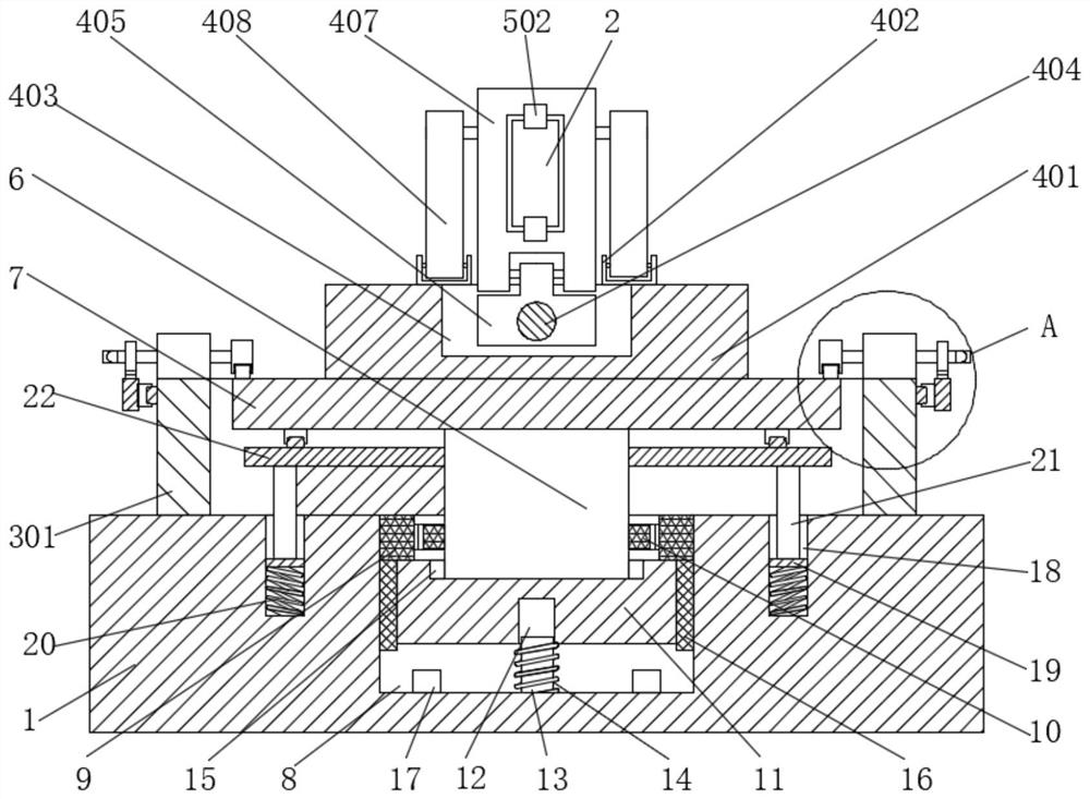
[0036] refer to Figure 1-7, an adjustable 5G antenna installation base, including a base 1, the top of the base 1 is sequentially provided with a pressing device 3, an angle adjustment device 4, and a fixing device 5, and the base 1 is provided with a circular groove 8, The 5G antenna 2 is fixedly installed in the fixing device 5, and the angle adjusting device 4 is used to adjust the angle of the 5G antenna 2. The inner walls on both sides of the circular groove 8 are slidably connected with a sliding block 11, and the top center of the sliding block 11 is rotatably connected with a rotating shaft. 6. The top of the rotating shaft 6 runs through the circular groove 8 and extends to the top of the base 1. The inner wall of the circular groove 8 is fixedly connected with a fixed gear ring 9, and the outer wall of the rotating shaft 6 is fixed with a fixed gear 10, and the fixed gear ring 9 Engaged with the fixed gear 10, the bottom of the sliding block 11 is provided with a gr...

Embodiment 2

[0038] This embodiment is improved on the basis of Embodiment 1:

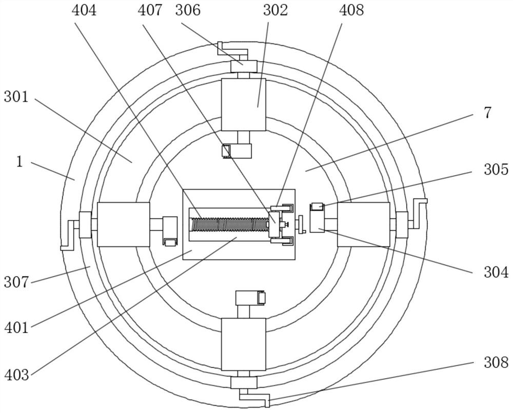
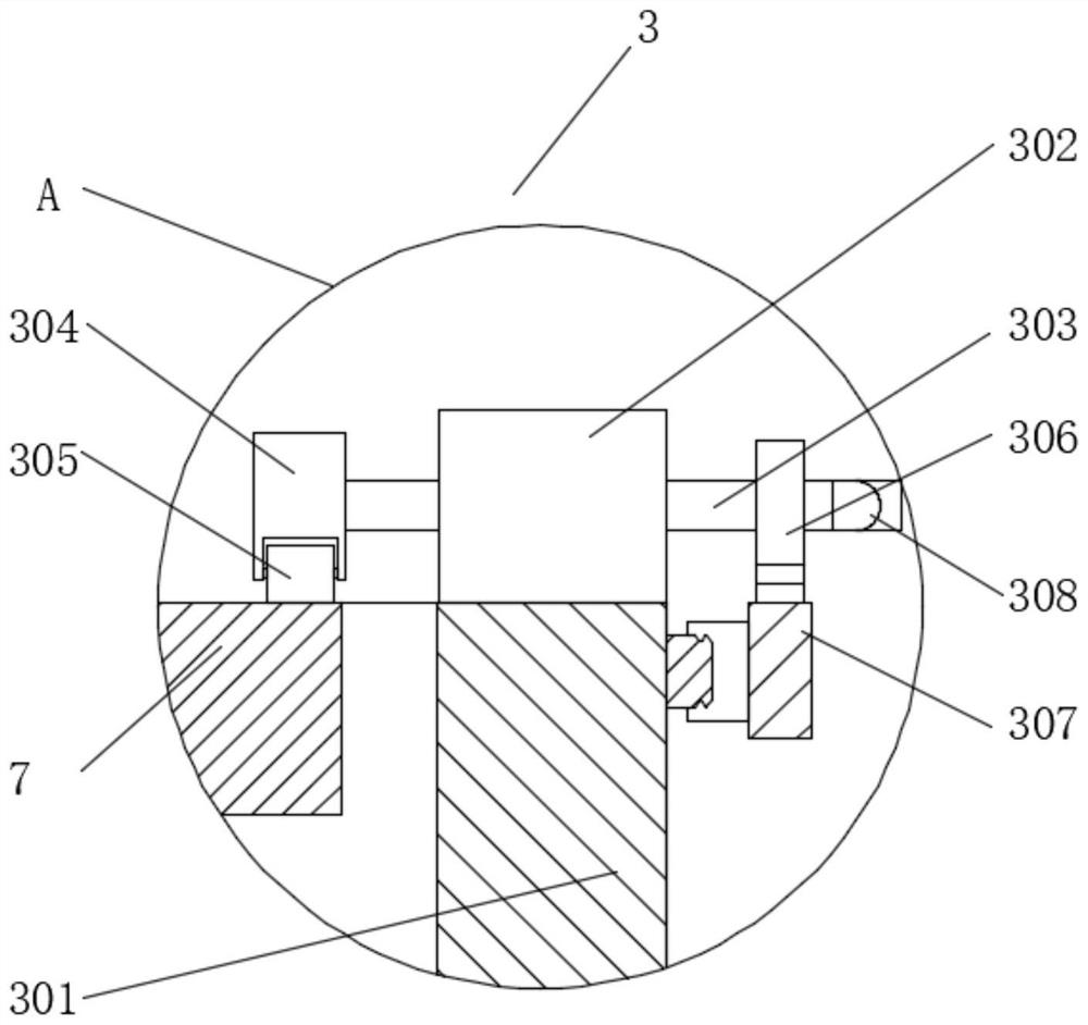
[0039] In the present invention, the pressing device 3 includes a circular platform 301 fixedly installed on the top of the base 1, and the top of the circular platform 301 is fixedly equipped with a plurality of rotating seats 302 arranged equidistantly in a ring with the rotating shaft 6 as the center of the circle. The rotating base 302 is rotatably connected with a rotating shaft 303, and the end of the rotating shaft 303 near the rotating plate 7 runs through the rotating base 302 and is fixedly connected with a rotating rod 304. One end away from the rotating plate 7 is fixedly connected with a gear 306, one end of the rotating shaft 303 runs through the gear 306 and is fixedly connected with a rotating handle 308, and the outer wall of the ring platform 301 is slidably connected with an annular rack 307, and the annular rack 307 and the gear 306 Mesh with each other, when the gear 306 rotates, it can dri...


PUM


Abstract

The invention belongs to the field of 5G antennas, particularly relates to an adjustable 5G antenna mounting base, and aims to solve the problem that the existing direction and angle cannot be adjusted. The adjustable 5G antenna mounting base comprises a base, the top of the base is sequentially provided with a pressing device, an angle adjusting device and a fixing device from bottom to top, and a circular groove is formed in the base; a 5G antenna is fixedly installed in the fixing device, the angle adjusting device is used for adjusting the angle of the 5G antenna, sliding blocks are slidably connected to the inner walls of the two sides of the circular groove, rotating shafts are rotatably connected to the center positions of the tops of the sliding blocks, and the top ends of the rotating shafts penetrate through the circular groove and extend to the position above the base. The angle and the direction of the 5G antenna can be easily adjusted by rotating the rotating disc and the rotating plate, the 5G antenna can be fixed more firmly through the bolt, the 5G antenna can be installed in high buildings, mansions and mountain fluctuation areas, and the installation difficulty of the 5G antenna is reduced.

Description

technical field [0001] The invention relates to the technical field of 5G antennas, in particular to an adjustable 5G antenna mounting base and a 5G antenna. Background technique [0002] The 5G network is called the fifth-generation mobile communication network, and its transmission speed is hundreds of times faster than that of the 4G network. With the development of the communication industry, 5G technology is gradually applied to life, but in the design of the 5G mobile communication network According to actual conditions such as network coverage requirements, traffic distribution, anti-interference requirements, and network service quality, a suitable base station antenna can be reasonably selected to prevent the 5G network from being interfered by terrain and ground objects. [0003] The current 5G antenna installation base is basically a uniform style, and does not have the adjustment of direction and angle, so the corresponding direction and angle cannot be adjusted ...

Claims


Application Information

Patent Timeline
Patent Type & Authority Applications(China)
IPC IPC(8): H01Q1/00H01Q1/12H01Q3/08
CPCH01Q1/12H01Q1/005H01Q3/08
Inventor 袁佳豪
Owner 袁佳豪
Learn More