
Capping device for oil drum in workshop

A technology for oil drums and equipment, which is applied in the field of oil drum capping equipment for workshops, can solve the problems of low capping efficiency, long time-consuming capping, and large energy consumption, so as to reduce trouble, reduce physical strength, and reduce burden Effect

Pending Publication Date: 2021-05-28
杨政年
View PDF10 Cites 1 Cited by
  • Summary
  • Abstract
  • Description
  • Claims
  • Application Information

AI Technical Summary

Problems solved by technology

[0005] In order to overcome the current oil drum capping equipment that not only consumes a lot of physical strength, but also takes a long time to cap and has low capping efficiency, the technical problem of the present invention is: to provide a high-efficiency Oil drum capping equipment for workshop

Method used


Image

  • Capping device for oil drum in workshop
  • Capping device for oil drum in workshop
  • Capping device for oil drum in workshop

Examples


Embodiment 1

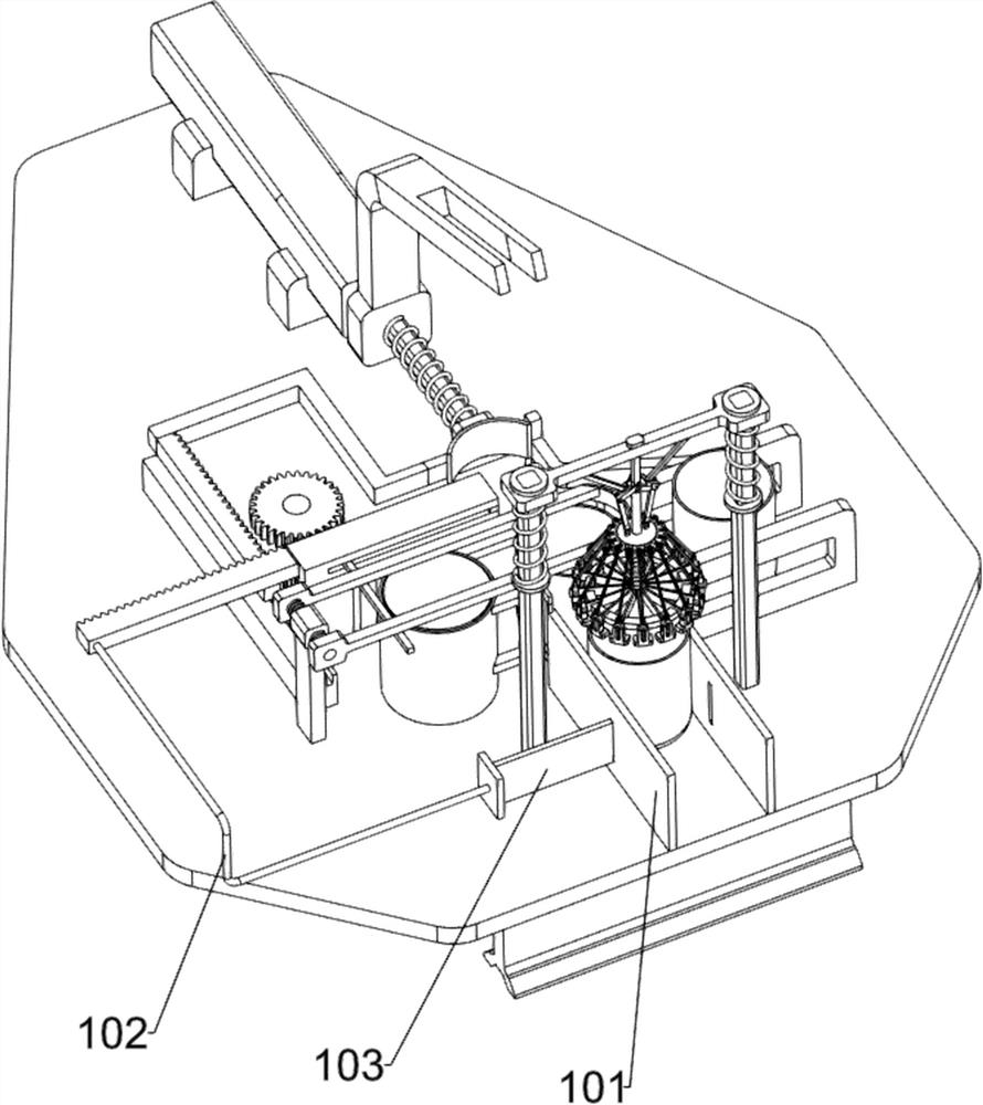
[0031] A workshop oil drum capping equipment, such as figure 1 and figure 2 As shown, it includes a base 1, a support block 2, a pressing mechanism 3 and an edge banding mechanism 4. The front side of the base 1 is fixed with two front and rear support blocks 2 by screws, and a pressing mechanism 3 is provided on the rear upper side of the base 1. , The pressing mechanism 3 is provided with an edge banding mechanism 4 .

[0032] When the oil barrel needs to be sealed, the oil barrel cover is placed on the oil barrel, and then the oil barrel is moved to the pressing mechanism 3 times, and then the edge sealing mechanism 4 is controlled, and the edge sealing mechanism 4 will seal the oil barrel After the oil barrel is capped, the edge banding mechanism 4 is no longer controlled, and the pressing mechanism 3 will drive the edge banding mechanism 4 to automatically reset, then remove the capped oil barrel, and then repeat the above operations.

[0033] The pressing mechanism 3 ...

Embodiment 2

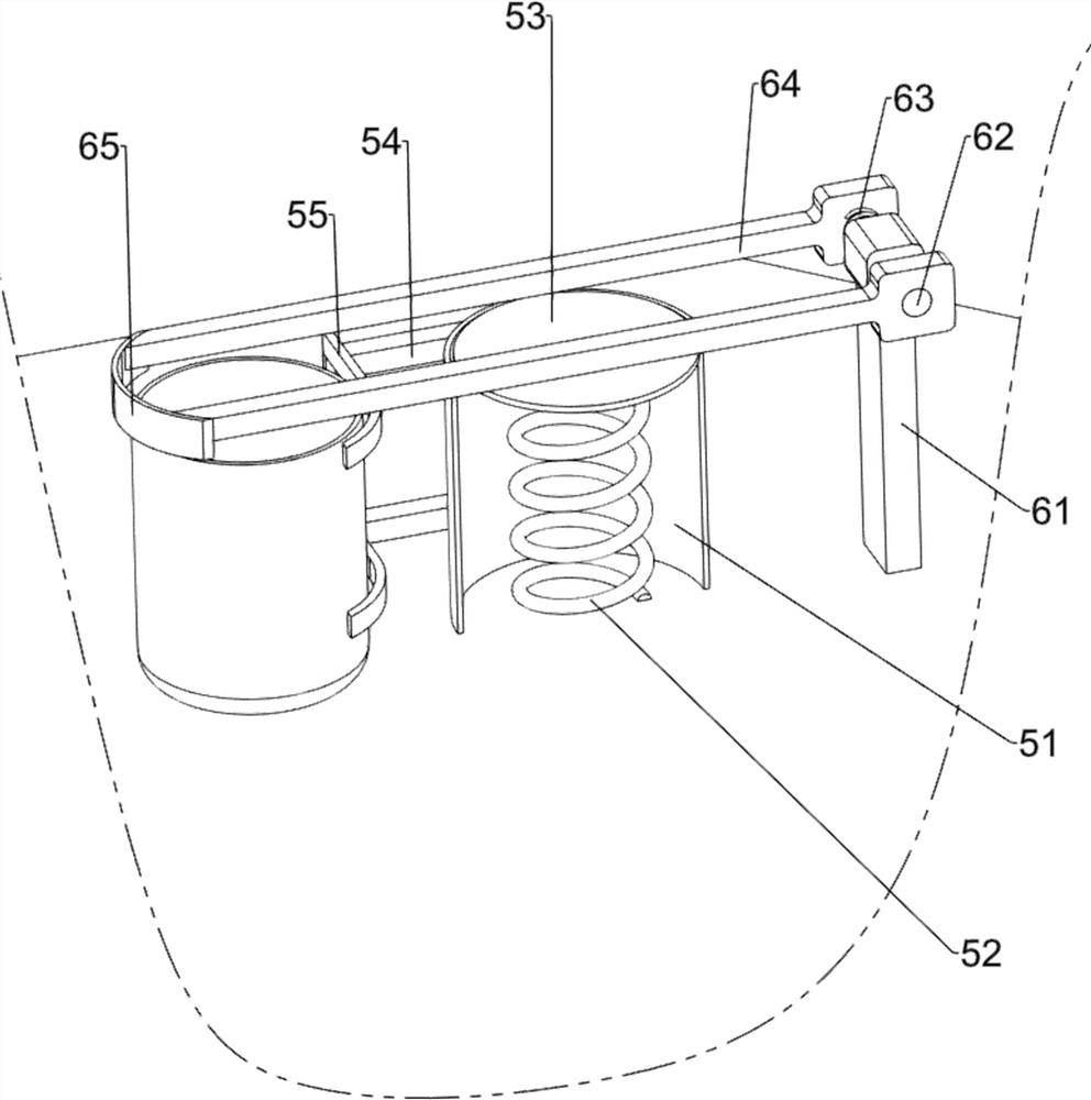
[0038] On the basis of Example 1, such as figure 1 , image 3 , Figure 4 , Figure 5 , Figure 6 and Figure 7 As shown, a bung storage mechanism 5 is also included, and the bung storage mechanism 5 includes a discharge barrel 51, a third spring 52, a placement plate 53, a third connecting rod 54 and a first stop 55, and the upper side of the base 1 A discharge barrel 51 is provided, the bottom in the discharge barrel 51 is connected with a third spring 52, and the upper side of the third spring 52 is connected with a placement plate 53, and the placement plate 53 cooperates with the discharge barrel 51, and the left side of the discharge barrel 51 A third connecting rod 54 is connected to the front and rear sides of the front part, and a first block 55 is connected between the left side of the third connecting rod 54 .

[0039] When the oil barrel needs to be sealed, the oil barrel lid is placed on the placement plate 53, and the third spring 52 will be deformed. When a...


PUM


Abstract

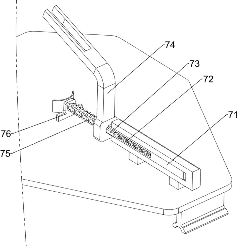
The invention relates to a capping device, in particular to a capping device for an oil drum in a workshop. The technical program to be solved by the invention is to provide the capping device for the oil drum in the workshop. The capping device does not consume physical strength and is high in efficiency. The capping device for the oil drum in the workshop comprises a base; two support blocks mounted on the base; a pressing mechanism mounted on the base; and an edge sealing mechanism mounted on the pressing mechanism. The capping device is provided with a drum cap storage mechanism, a drum cap can be bounced automatically under the acting force of a third spring so as to be conveniently stored by a worker. The capping device is provided with a limiting mechanism, the drum cap can be accurately placed on the oil drum under the effect of a second baffle, so that the situation that the capping effect is affected due to the fact that the drum cap cannot be accurately placed is prevented. The capping device is provided with a pushing mechanism, and the oil drum does not need to be manually moved and a first sliding rod does not need to be controlled to move by controlling a cylinder when the device is used, so that the burden of the worker is reduced.

Description

technical field [0001] The invention relates to a capping device, in particular to a capping device for an oil barrel used in a workshop. Background technique [0002] Oil barrels, that is, oil barrels, are generally made of iron or plastic in a cylindrical shape. They were originally invented by the Germans on the eve of World War II. They are mainly used to carry important military supplies. They can be said to be typical war products. [0003] Generally, oil drums need to be capped after filling oil, and the general oil drum capping equipment needs to be manually operated. When capping, people need to manually place the oil drum cap on the oil drum, and then the staff will Holding the oil drum capping equipment in hand and placing it on the oil drum, and then manually controlling the oil drum capping equipment to seal it, it not only takes a lot of physical strength to use this device, but also takes a long time to seal, sealing The cover is less efficient. [0004] The...

Claims


Application Information

Patent Timeline
Patent Type & Authority Applications(China)
IPC IPC(8): B67B3/00B67B3/06
CPCB67B3/00B67B3/06
Inventor 杨政年
Owner 杨政年
Learn More