Filling equipment of injection molding machine
A technology for injection molding machines and equipment, applied in the field of injection molding machine filling equipment, can solve the problems of affecting work progress, high labor intensity, unsuitable for large-scale production, etc., and achieve the effect of saving resources
- Summary
- Abstract
- Description
- Claims
- Application Information
AI Technical Summary
Problems solved by technology
Method used
Image
Examples
Embodiment 1
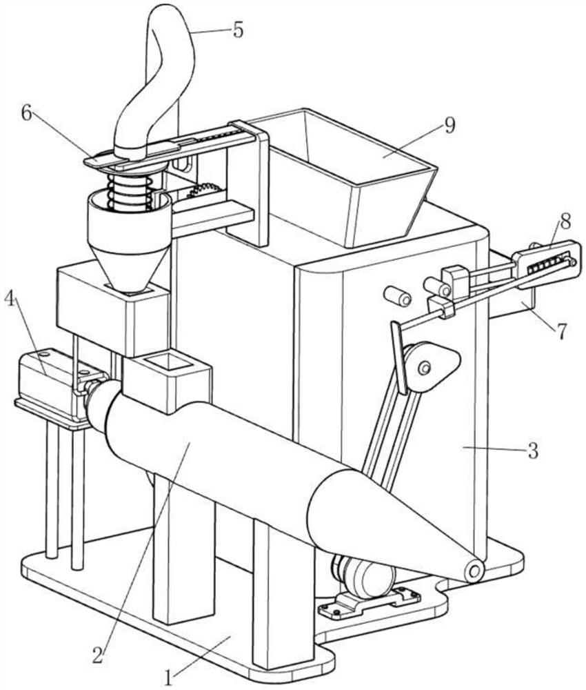
[0075] An injection molding machine filling device, such as figure 1 As shown, it includes a bottom plate 1, a melting device 2, a storage bin 3, a filling assembly 4 and an automatic feeding assembly 5. The bottom plate 1 is provided with a melting device 2 on the left side, and the bottom plate 1 is provided with a storage bin 3 on the right side. A filling assembly 4 is provided between the rear side of the upper left part of 1 and the rear side of the melting device 2, and an automatic feeding assembly 5 is provided between the storage bin 3 and the bottom plate 1.
[0076] When people need to fill the injection molding machine, this injection molding machine filling equipment can be used. First, people need to pour the plastic into the storage bin 3, and then start the automatic feeding assembly 5. The automatic feeding assembly 5 runs so that the plastic can be sent to the On the filling assembly 4, close the automatic feeding assembly 5 when feeding is not needed, and t...
Embodiment 2
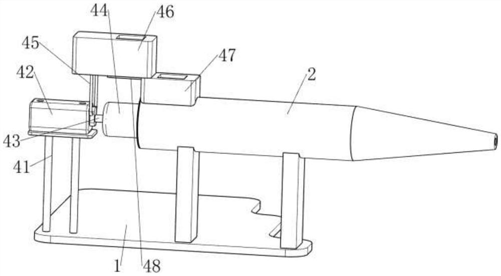
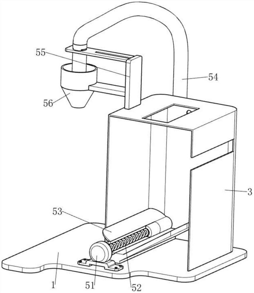
[0078] On the basis of Example 1, such as figure 2 and image 3 As shown, the packing assembly 4 includes a first support frame 41, a cylinder 42, a push rod 43, a push block 44, a connecting rod 45, a feeding block 46, a lower chute 47 and a first baffle plate 48. The side is provided with a first support frame 41, a cylinder 42 is installed on the top of the first support frame 41, a push rod 43 is provided on the telescopic rod of the cylinder 42, and a push block 44 is provided on the front side of the push rod 43, and the push block 44 and the melting device 2 Sliding connection, the rear side of the push rod 43 is provided with a connecting rod 45, the rear side of the melting device 2 is provided with a feeding chute 47, and the upper side of the feeding chute 47 is provided with a first baffle 48, and the first baffle 48 and the lower A feed block 46 is slidably provided between the tops of the troughs 47 , and the feed block 46 is fixedly connected with the connecti...
Embodiment 3
[0083] On the basis of Example 2, such as Figure 4-Figure 9 As shown, it also includes a material breaking assembly 6, which includes a limiting plate 61, a first wedge block 62, a spring 63, a second wedge block 64, a first telescopic assembly 65, and a material breaking plate 66, and the feeding pipe 54, the upper and lower sides of the left part are provided with limiting plates 61, the limiting plate 61 on the lower side is slidably connected with the feed pipe 54, and the top of the right side of the limiting plate 61 on the lower side is provided with a first wedge block 62, and the second supporting The inner wall of the upper side of the frame 55 is provided with a first telescopic assembly 65, and the left side of the first telescopic assembly 65 is provided with a second wedge block 64. The first telescopic assembly 65 is composed of a first telescopic rod and a first spring, and the first spring is wound around the second On a telescopic rod, the two ends of the fi...
PUM
 Abstract
Description
Claims
Application Information
 - R&D
- Intellectual Property
- Life Sciences
- Materials
- Tech Scout
- Unparalleled Data Quality
- Higher Quality Content
- 60% Fewer Hallucinations
Browse by: Latest US Patents, China's latest patents, Technical Efficacy Thesaurus, Application Domain, Technology Topic, Popular Technical Reports.
© 2025 PatSnap. All rights reserved.Legal|Privacy policy|Modern Slavery Act Transparency Statement|Sitemap|About US| Contact US: help@patsnap.com


