Round block cutting equipment for round chopping board processing
A technology for cutting equipment and cutting boards, which is applied to the field of circular block cutting equipment for processing circular cutting boards, achieves the effects of reducing workload, facilitating circular cutting work, and improving cutting efficiency
- Summary
- Abstract
- Description
- Claims
- Application Information
AI Technical Summary
Problems solved by technology
Method used
Image
Examples
Embodiment 1
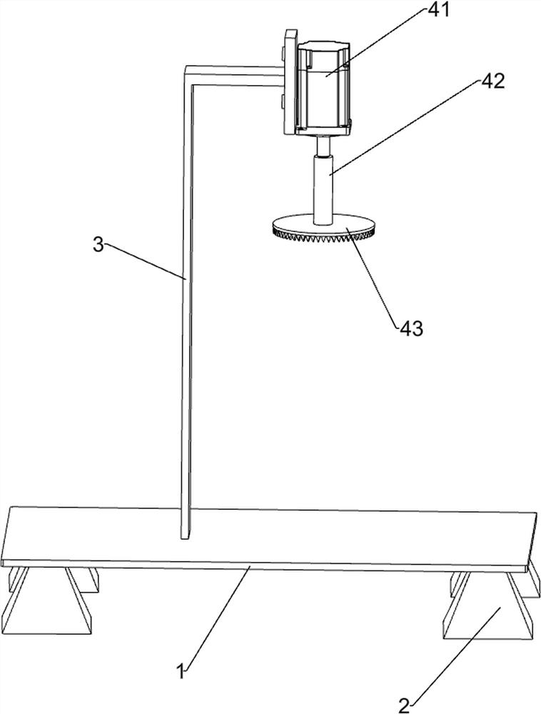
[0025] A kind of circular block cutting equipment for processing circular chopping boards, such as Figure 1-3 As shown, it includes a bottom plate 1, a base 2, a bracket 3, a cutting mechanism 4 and a lifting mechanism 5, the four corners of the bottom of the bottom plate 1 are connected with a base 2, the left side of the top of the bottom plate 1 is connected with a bracket 3, and a cutting mechanism is installed on the bracket 3 4. A lifting mechanism 5 is installed on the top of the bottom plate 1 .
[0026] Cutting mechanism 4 comprises high-speed motor 41, rotating shaft 42 and cutting knife 43, and high-speed motor 41 is installed on support 3 tops, and the output shaft of high-speed motor 41 is connected with rotating shaft 42 by coupling, and rotating shaft 42 bottom ends are connected with cutting knife 43.
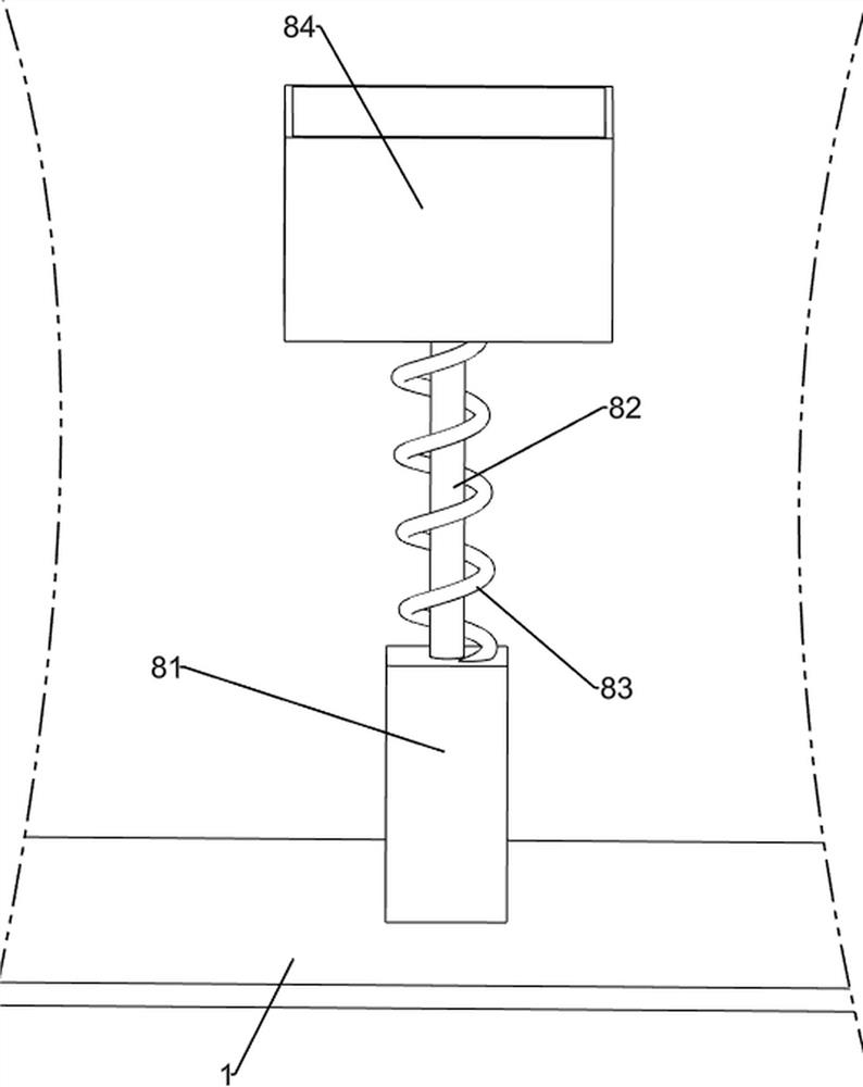
[0027] Lifting mechanism 5 comprises connecting column 51, the first spring 52, slide block 53, handle 54, connecting plate 55, connecting block 56 and chassis...
Embodiment 2
[0030] On the basis of Example 1, such as figure 1 , image 3 with Figure 4 As shown, it also includes a driving mechanism 6, and the driving mechanism 6 includes a geared motor 61, a support block 62, a rotating rod 63, a belt drive assembly 64, a missing gear 65, a slide rail 66, a carriage 67, a rack 68, a second Spring 69 and slide bar 610, bottom plate 1 top left rear side is equipped with deceleration motor 61, bottom plate 1 top left side is connected with support block 62, and support block 62 is positioned at the left side of support 3, and support block 62 is connected with rotating rod 63, a belt transmission assembly 64 is connected between the rotating rod 63 and the output shaft of the reduction motor 61, the rotating rod 63 is connected with a missing gear 65, the front side of the bottom plate 1 top is connected with a slide rail 66, and the slide rail 66 is slidingly connected with Sliding frame 67, there is a word groove on the sliding frame 67, the left s...
Embodiment 3
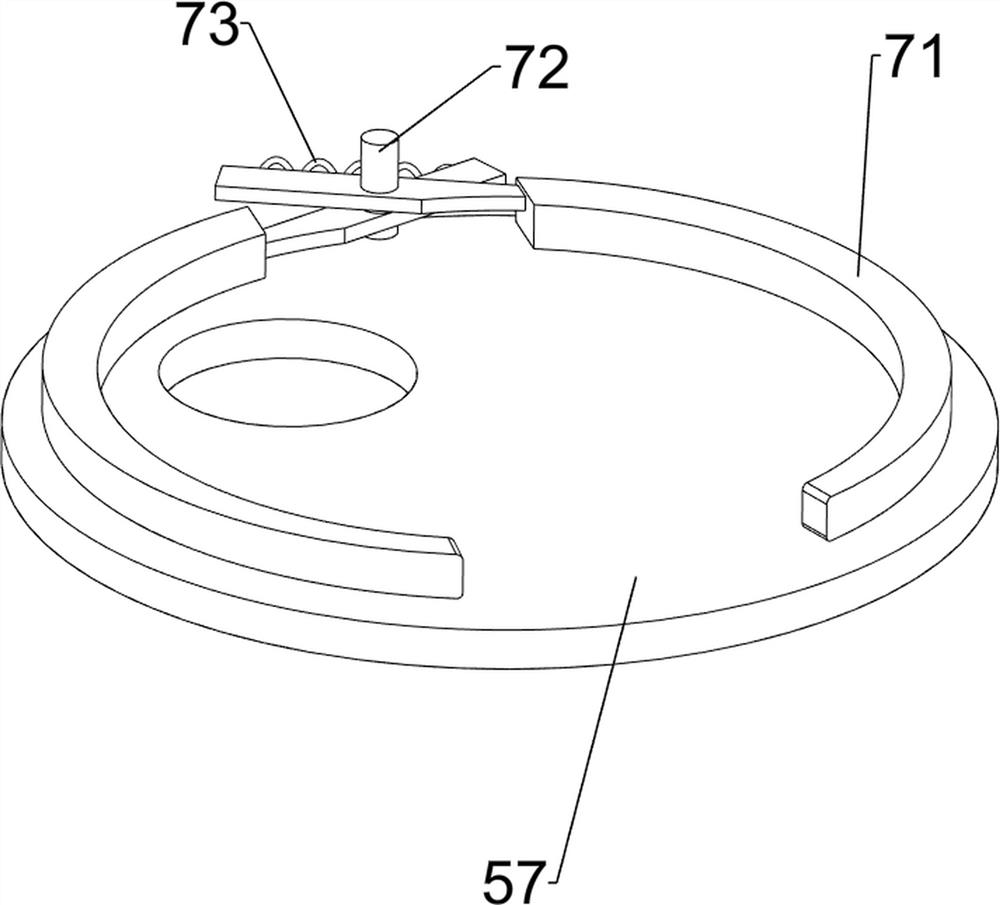
[0033] On the basis of Example 2, such as figure 1 with Figure 5 As shown, a fixing mechanism 7 is also included. The fixing mechanism 7 includes a splint 71, a fixed shaft 72 and a third spring 73. The rear side of the top of the chassis 57 is connected with a fixed shaft 72, and the fixed shaft 72 is rotatably connected with two splints 71. , A third spring 73 is connected between the two splints 71 .
[0034] Initially, the two clamping plates 71 are closed, and the two clamping plates 71 can be manually separated from each other, and the third spring 73 is stretched thereupon, and then a large circular plank can be placed between the two clamping plates 71. Under the effect of the third spring 73, two splints 71 can be clamped and fixed by the large circular plank, which can prevent the large circular plank from moving voluntarily, thereby making it easy to carry out the circle cutting work; The large circular wooden board can be clamped and fixed to prevent the large c...
PUM
 Abstract
Description
Claims
Application Information
 - R&D Engineer
- R&D Manager
- IP Professional
- Industry Leading Data Capabilities
- Powerful AI technology
- Patent DNA Extraction
Browse by: Latest US Patents, China's latest patents, Technical Efficacy Thesaurus, Application Domain, Technology Topic, Popular Technical Reports.
© 2024 PatSnap. All rights reserved.Legal|Privacy policy|Modern Slavery Act Transparency Statement|Sitemap|About US| Contact US: help@patsnap.com


