
Detection method, detection device, detection system and radar

A detection method and detection frame technology, applied in the field of radar, can solve the problems of affecting the interference avoidance effect, less listening time, and poor listening effect, etc.

Active Publication Date: 2021-05-25
HUAWEI TECH CO LTD
View PDF5 Cites 0 Cited by
  • Summary
  • Abstract
  • Description
  • Claims
  • Application Information

AI Technical Summary

Problems solved by technology

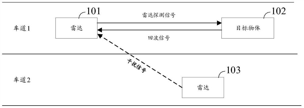
However, the interference interception technology needs to have sufficient time for interception in order to judge the resource occupancy more accurately. In some scenarios, such as intersections, T-shaped intersections, etc. Blocking) to form a non-line of sight (NLOS) situation, only when vehicles in different directions approach or turn, and the field of view (FOV) has a large overlap can they detect each other's signals , that is, there is less time left for listening, which makes the listening effect poor and affects the final interference avoidance effect

Method used


Image

  • Detection method, detection device, detection system and radar
  • Detection method, detection device, detection system and radar
  • Detection method, detection device, detection system and radar

Examples


Embodiment approach 1

[0288] Embodiment 1: The second signal is transmitted within the detection time of the detection frame, and the second signal belongs to the first detection signal of the first detection device. see Figure 16 , Figure 16 is a schematic diagram of a signal transmitted by the first detection device to the second direction provided by the embodiment of the present application, wherein, see Figure 16 part (a) of Figure 16 Part (a) exemplifies a schematic diagram of the detection signal of the first detection device in the second direction, wherein: t0 to t3 can be regarded as the period of a detection frame of the first detection device, and the period between t1 and t2 is The detection time is an idle time between t0 and t1 and between t2 and t3, during which the first detection device can transmit a first detection signal, receive an echo signal, and the like. After listening to at least one signal in at least one direction, the first detecting device may configure the ti...

Embodiment approach 2

[0292] Embodiment 2: The first detection device transmits a detection signal during the detection time of the detection frame, and transmits the second signal during the idle time of the detection frame. see Figure 17 , Figure 17 is a schematic diagram of a signal transmitted by the first detection device to the second direction provided by the embodiment of the present application, wherein, Figure 17 Part (a) exemplifies a schematic diagram of the original first detection signal of the first detection device (for a specific description, please refer to Figure 16 The description of part (a) in). See Figure 17 In part (b) of the first detection device, the first detection device may transmit the first detection signal within the detection time (such as t8-t9, t13-t14), and transmit the first detection signal within a period of idle time (such as t10-t11, t15-t16). Two signals. That is to say, on the one hand, the first detection device transmits the first detection si...

Embodiment approach 3

[0294] Embodiment 3: The detection frame includes a first detection frame and a second detection frame. The first detection device transmits a detection signal at the detection time of the first detection frame, and transmits the second signal at the detection time of the second detection frame. see Figure 18 , Figure 18 is a schematic diagram of a signal emitted by a first detection device provided in an embodiment of the present application, wherein, see Figure 18 part (a) of Figure 18 Part (a) exemplifies a schematic diagram of the original first detection signal of the first detection device (for a specific description, please refer to Figure 16 The description of part (a) in). See Figure 18 (b) part, the first detection device can transmit the detection signal to the second direction at the detection time (such as t8-t9) of the detection frame 7 (ie, the aforementioned first detection frame), and in the detection frame 8 (the aforementioned second detection fra...


PUM


Abstract

The embodiment of the invention provides a detection method, a detection device, a detection system and a radar, and the method comprises the steps: monitoring at least one signal from at least one direction, wherein the at least one signal comprises a first signal corresponding to a first direction; transmitting a second signal to a second direction, wherein the second signal is used for indicating the predicted interference time-frequency range; wherein the time-frequency range of the first signal and the time-frequency range of the second signal meet at least one of the following conditions: the frequency domain range of the first signal is a subset of the frequency domain range of the second signal; alternatively, the time domain range of the first signal is a subset of the time domain range of the second signal. The interference time-frequency range can be indicated to the second direction in the form of transmitting the second signal, so that the second detection device obtains the interference time-frequency range of a non-line-of-sight area, and the target detection accuracy of the second detection device is improved. The scheme can be further applied to the field of automatic driving, intelligent driving or unmanned driving, the interference avoidance capability of the vehicle is improved, and the driving safety of the vehicle is improved.

Description

technical field [0001] The present application relates to radar technology, which is applied to the fusion perception field of automatic driving or intelligent driving, and in particular relates to a detection method, detection device, detection system and radar. Background technique [0002] With the development of society, smart cars are gradually entering people's daily life. Sensors play a very important role in assisted driving and automatic driving of smart cars. Various sensors installed on the car, such as millimeter-wave radar, lidar, ultrasonic radar, camera, etc., can perceive the surrounding environment, identify and track moving objects, and identify static scenes (such as lanes) while the car is driving. lines, signs). In a word, sensors can detect possible dangers in advance and help drivers in time, and take necessary avoidance measures, effectively increasing the safety and comfort of car driving. [0003] Among them, vehicle-mounted radar is an important...

Claims


Application Information

Patent Timeline
IPC IPC(8): G01S13/931G01S7/02G01S7/41
CPCG01S13/931G01S7/021G01S7/023G01S7/41G01S7/418
Inventor 宋思达马莎
Owner HUAWEI TECH CO LTD
Learn More