Method and device for extracting defect area on board surface

An extraction method and an extraction device technology, which are applied in the field of extraction of defect areas on board surfaces, can solve problems such as the inability to meet the running speed of a production line, increase in missed detection rate and false detection rate, and long calculation time, so as to save the time required for detection, The effect of reducing time and improving accuracy

Active Publication Date: 2022-07-22
SHANDONG JIANZHU UNIV +1
View PDF2 Cites 0 Cited by
  • Summary
  • Abstract
  • Description
  • Claims
  • Application Information

AI Technical Summary

Problems solved by technology

In the existing technology, the size of the image generally collected is about 2560×2048 pixels, the amount of data is large, and the calculation takes a long time, which cannot meet the running speed of the production line
If the calculation speed is increased to adapt to the running speed of the production line, the only way to reduce the amount of calculation is to reduce the detection accuracy, but this may increase the missed detection rate and false detection rate.

Method used


Image

  • Method and device for extracting defect area on board surface
  • Method and device for extracting defect area on board surface
  • Method and device for extracting defect area on board surface

Examples


Embodiment 1

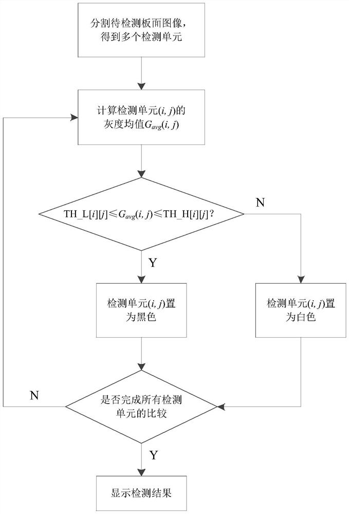
[0057] like figure 1 As shown, this embodiment provides a method for extracting a defect area on a board surface, including:

[0058] Obtain and segment the image of the board to be detected to obtain multiple detection units;

[0059] Obtain the grayscale thresholds corresponding to the multiple detection units one-to-one;

[0060] Calculate the average gray level of the detection unit and compare it with the corresponding gray level threshold to determine whether the detection unit contains a defect.

[0061] In the above solution, by dividing the image of the board surface to be inspected into a plurality of inspection units, for each inspection unit, there is a corresponding grayscale threshold for judging whether a defect is contained therein, which improves the accuracy of the judgment result. . At the same time, all the detection units containing defects together form the defect area on the board surface. When further identification of defects is performed, only the ...

Embodiment 2

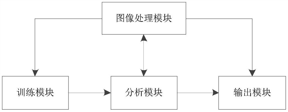
[0096] like image 3 As shown, this embodiment provides a device for extracting a defect area on a board surface, which is used to implement the method for extracting a defect area on a board surface described in the first embodiment. The extraction device for the defect area of ​​the board surface includes:

[0097] The image processing module is used to segment the image of the panel to be detected to obtain a plurality of detection units;

[0098] The analysis module is connected with the image processing module, and is used for calculating the grayscale mean value of the detection unit and comparing it with the obtained grayscale threshold value to judge whether the detection unit contains defects.

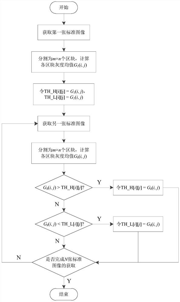
[0099] Further, the grayscale threshold includes a high threshold and a low threshold, and the device for extracting the defect area on the board surface further includes a training module.

[0100] The training module is connected with the analysis module, and is used to ob...


PUM


Abstract

The invention belongs to the technical field of industrial inspection, and discloses a method and a device for extracting a defect area on a board surface. The method for extracting a defect area on a board surface includes: acquiring and dividing an image of the board surface to be detected to obtain a plurality of detection units; Grayscale thresholds corresponding to multiple detection units one-to-one; calculate the grayscale mean of the detection units and compare them with the corresponding grayscale thresholds to determine whether the detection units contain defects. The invention divides the image of the board surface to be detected into a plurality of detection units, and judges whether each detection unit contains a defect, thereby improving the accuracy of the judgment result. When the defect is further identified, only the detection unit containing the defect can be analyzed, which greatly reduces the amount of data that needs to be processed, thereby reducing the time required for defect detection on the board surface.

Description

technical field [0001] The invention belongs to the technical field of industrial inspection, and in particular relates to a method and device for extracting defect areas on a board surface. Background technique [0002] Whether there are defects on the board surface of the board is one of the standards to measure the quality of the board. Generally, the board surface defect detection is carried out directly on the production line to judge whether the produced board is qualified. Taking particleboard as an example, the most advanced particleboard production equipment is the continuous press production line. Machine vision technology is currently the mainstream of industrial non-destructive testing technology, but in the field of plate surface defect detection, there is still a lack of relatively mature systems to realize the application of machine vision technology. Therefore, at present, most particleboard manufacturers still rely on workers to inspect with the naked eye o...

Claims


Application Information

Patent Timeline
Patent Type & Authority Patents(China)
IPC IPC(8): G06T7/00G06T7/11G06T7/136G06T3/40G06T7/187
CPCG06T7/0008G06T7/11G06T7/136G06T7/187G06T3/4038G06T2207/10004G06T2200/32
Inventor 周玉成赵子宇王永正陈龙现刘传泽
Owner SHANDONG JIANZHU UNIV
Why Eureka
Try Eureka