Ultrasonic treatment device

A processing device and ultrasonic processing technology, applied in the direction of fluid using vibration, etc., can solve the problem of poor connection between power ultrasonic components and processed parts

Pending Publication Date: 2021-05-25
NINGBO INST OF MATERIALS TECH & ENG CHINESE ACADEMY OF SCI
View PDF6 Cites 3 Cited by
  • Summary
  • Abstract
  • Description
  • Claims
  • Application Information

AI Technical Summary

Problems solved by technology

[0008] In view of this, the object of the present invention is to provide an ultrasonic processing device, which can effectively solve the problem of poor connection between the power ultrasonic components and the treated object

Method used


Image

  • Ultrasonic treatment device
  • Ultrasonic treatment device

Examples


Embodiment Construction

[0026] The embodiment of the present invention discloses an ultrasonic processing device to effectively solve the problem of poor connection between the power ultrasonic component and the object to be treated.

[0027] The following will clearly and completely describe the technical solutions in the embodiments of the present invention with reference to the accompanying drawings in the embodiments of the present invention. Obviously, the described embodiments are only some, not all, embodiments of the present invention. Based on the embodiments of the present invention, all other embodiments obtained by persons of ordinary skill in the art without making creative efforts belong to the protection scope of the present invention.

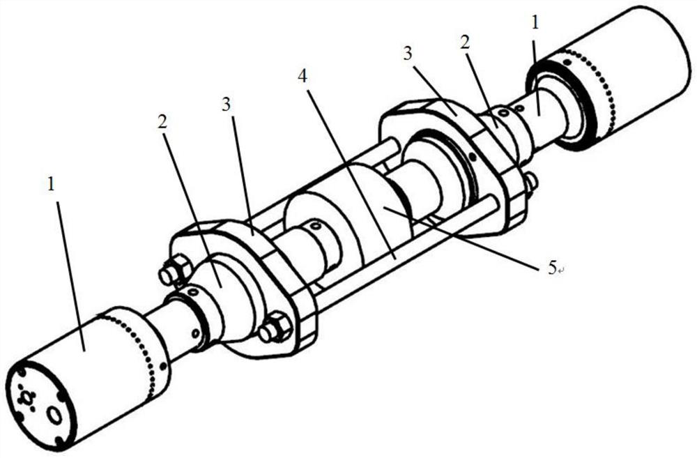
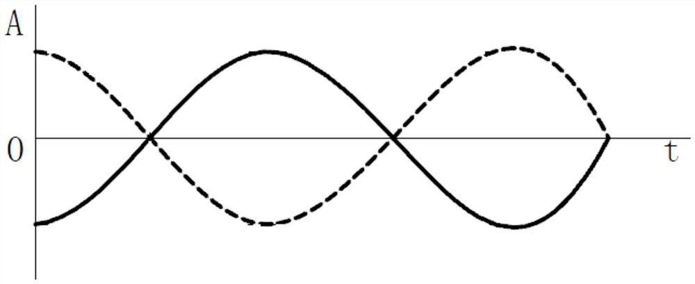
[0028] see Figure 1-Figure 2 , figure 1 Schematic diagram of the structure of the ultrasonic treatment device provided by the embodiment of the present invention; figure 2 The time-sound wave amplitude coordinate axis diagram of two groups of ultra...


PUM


Abstract

The invention discloses an ultrasonic treatment device. The ultrasonic treatment device is characterized by comprising two groups of ultrasonic treatment components with sound wave phases capable of being staggered and a clamping driving mechanism for driving the two groups of ultrasonic treatment components to approach to each other in order to enable ultrasonic heads to clamp a treated part. In the ultrasonic treatment device, through the clamping driving mechanism, tight contact with the treated part can be achieved, the ultrasonic transmission effect is guaranteed, the treated part does not need to be damaged, and the overall operation is simple. The sound waves of the two groups of ultrasonic treatment components have a phase difference, so that the amplitudes of the two ultrasonic heads are amplified, the treated part is better excited, better ultrasonic treatment is realized, and the treatment such as cleaning, destressing and machining can be realized. In conclusion, the ultrasonic treatment device can effectively solve the problem that the connection effect of a power ultrasonic part and the treated part is poor.

Description

technical field [0001] The present invention relates to the technical field of ultrasonic treatment, and more specifically, relates to an ultrasonic treatment device. Background technique [0002] In the fields of ultrasonic aging treatment technology, ultrasonic cleaning descaling, rust removal and other fields, it is often necessary to closely connect ultrasonic components such as ultrasonic transducer horns and processed parts. Currently, bonding, welding or hole bolts are used to connect. It is unreliable and also destroys the integrity of the processed parts, especially for pressure vessels or high-pressure pipeline equipment, the current process cannot meet the processing requirements. [0003] (1) Power ultrasonic application technology needs to connect the horn of the ultrasonic transducer to the workpiece to be processed. The connecting end surface must be completely fitted and have a certain pressure, otherwise it will affect the effective transmission of ultrasoni...

Claims


Application Information

Patent Timeline
Patent Type & Authority Applications(China)
IPC IPC(8): B06B1/06
CPCB06B1/06
Inventor 翟锰钢赵夙尚晓峰于磊
Owner NINGBO INST OF MATERIALS TECH & ENG CHINESE ACADEMY OF SCI
Why Eureka
Try Eureka