Safe waterproof power distribution cabinet
A power distribution cabinet and safety technology, applied in the field of safe waterproof power distribution cabinets, can solve the problems of waste of moisture-proof treatment resources and lack of sudden fires in power distribution cabinets.
- Summary
- Abstract
- Description
- Claims
- Application Information
AI Technical Summary
Problems solved by technology
Method used
Image

Examples
Embodiment 1
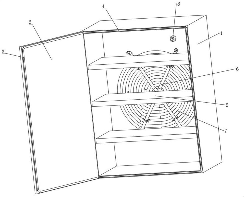
[0038] According to attached figure 1 and 2 As shown, a safe waterproof power distribution cabinet includes a cabinet body 1 and partitions 2 intermittently arranged in the inner cavity of the cabinet body 1. The edge of the front face of the cabinet body 1 is connected to the cabinet door 3 by rotation, and the cabinet door 3 is close to the cabinet body 1. One side of the cabinet is fixedly connected with a sealing strip 4, a sealing groove 5 is provided at the edge of the front end of the cabinet 1, a dehumidification device 6 is provided at the lower part of the rear end of the cabinet 1, and a cold water utilization device 7 is provided on the rear wall of the cabinet 1 , the upper part of the rear end surface of the cabinet body 1 is equipped with a fire extinguishing device 8 through the installation device 9;
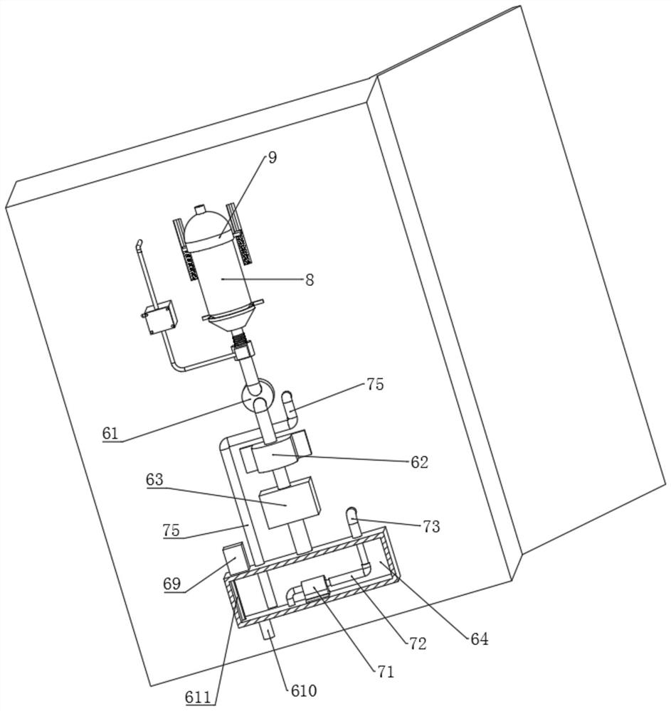
[0039] The dehumidification device 6 includes a main air intake pipe 61 arranged in the middle of the back chamber wall of the cabinet body 1. One end of the m...
Embodiment 2
[0044] The difference between this embodiment and other embodiments is that, according to the attached Figure 4 As shown, wherein, the number of suction pipes 66 is not less than six, and the suction pipes 66 are evenly arranged on the main air intake pipe 61 along the axis of the main air intake pipe 61. The inner cavity wall of the body 1 is detachably connected. By arranging no less than six suction pipes 66 evenly in a ring on the front end of the main air intake pipe 61, it can be effectively ensured that when the suction device 62 is started, the moisture at different positions in the inner cavity of the cabinet body 1 can be absorbed. Reduce the occurrence of moisture agglomeration in the cabinet, so as to affect the normal operation of electrical components in the power distribution cabinet.
Embodiment 3
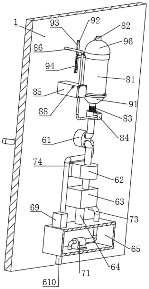
[0046] The difference between this embodiment and other embodiments is that, according to the attached image 3 and 4 As shown, wherein, the cold water utilization device 7 includes a micro-water pump 71 detachably connected in the cold water tank 65, the water outlet end of the micro-water pump 71 is connected with a water outlet pipe 72, and the end of the water outlet pipe 72 away from the micro-water pump 71 is connected with a circulating water inlet. Pipe 73, one end of the circulating water inlet pipe 73 away from the water outlet pipe 72 is connected with a helical pipe 74, and one end of the helical pipe 74 is communicated with the inner cavity of the cold water tank 65 through the circulating water outlet pipe 75. When the humidity sensor 68 detects that the humidity in the power distribution cabinet is too high, the signal receiving module and the control module in the first control box 69 cooperate with each other to start the air suction device 62 and the semicond...
PUM
 Abstract
Description
Claims
Application Information
 - R&D
- Intellectual Property
- Life Sciences
- Materials
- Tech Scout
- Unparalleled Data Quality
- Higher Quality Content
- 60% Fewer Hallucinations
Browse by: Latest US Patents, China's latest patents, Technical Efficacy Thesaurus, Application Domain, Technology Topic, Popular Technical Reports.
© 2025 PatSnap. All rights reserved.Legal|Privacy policy|Modern Slavery Act Transparency Statement|Sitemap|About US| Contact US: help@patsnap.com