
Mining robot system based on block chain

A robot system and blockchain technology, applied in the blockchain field, can solve problems such as the limitation of the retractable length of the plug rod, the space limitation of the excavation system of the excavation system, and the small rotating angle of the turntable.

Inactive Publication Date: 2021-05-18
陈培安
View PDF0 Cites 0 Cited by
  • Summary
  • Abstract
  • Description
  • Claims
  • Application Information

AI Technical Summary

Problems solved by technology

[0003] In the prior art, the roadheader is the main mining robot. The slewing system of the roadheader mining robot is rotated through the cooperation of the turntable gear and the plug rod of the telescopic cylinder. Since the telescopic length of the plug rod of the telescopic cylinder is limited , resulting in a small rotatable angle of the turntable, which limits the excavable space of the excavation system of the mining robot

Method used


Image

  • Mining robot system based on block chain
  • Mining robot system based on block chain
  • Mining robot system based on block chain

Examples


Embodiment 1

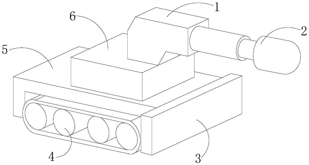
[0028] see Figure 1-Figure 5 , a blockchain-based mining robot system, its structure includes a swing arm 1, a tunneling head 2, a control panel 3, a driving body 4, a body 5, and a gyrator 6, and the swing arm 1 is mechanically connected to the tunneling head 2 , the swing arm 1 is movably engaged with the gyrator 6, the gyrator 6 is movably connected with the body 5 through a movable shaft, the body 5 is mechanically connected with the control panel 3, and the driving body 4 and the body 5 are fitted together ;

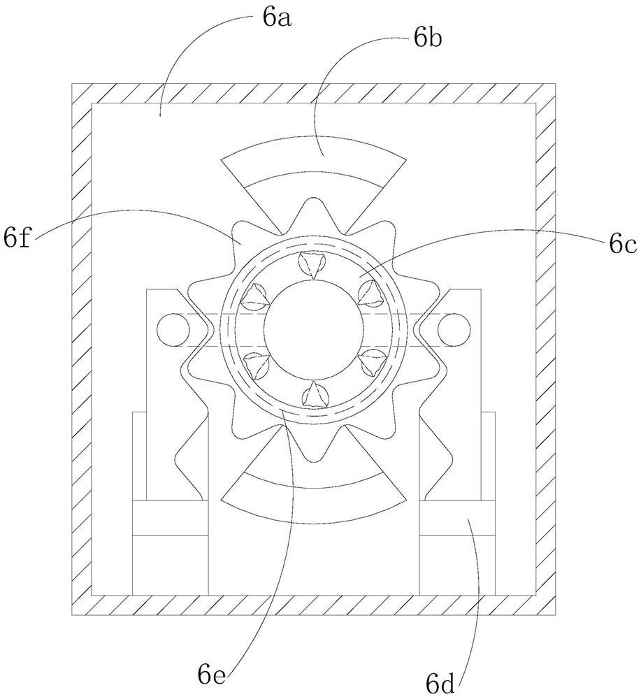
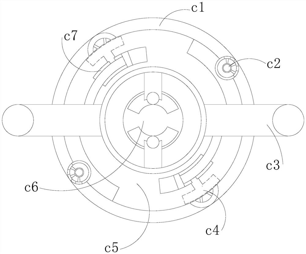
[0029] The gyrator 6 is provided with a box body 6a, a stabilizer 6b, an expander 6c, a telescopic oil cylinder 6d, a turntable 6e, and an external gear 6f. The box body 6a is mechanically connected to the telescopic oil cylinder 6d, and the telescopic oil cylinder 6d is connected to the outer gear The gear 6f is fitted, the external gear 6f is movably connected with the expander 6c through a movable shaft, the turntable 6e is movably engaged with the expander 6c,...

Embodiment 2

[0037] see Figure 1-Figure 5 , a blockchain-based mining robot system, its structure includes a swing arm 1, a tunneling head 2, a control panel 3, a driving body 4, a body 5, and a gyrator 6, and the swing arm 1 is mechanically connected to the tunneling head 2 , the swing arm 1 is movably engaged with the gyrator 6, the gyrator 6 is movably connected with the body 5 through a movable shaft, the body 5 is mechanically connected with the control panel 3, and the driving body 4 and the body 5 are fitted together ;

[0038] The gyrator 6 is provided with a box body 6a, a stabilizer 6b, an expander 6c, a telescopic oil cylinder 6d, a turntable 6e, and an external gear 6f. The box body 6a is mechanically connected to the telescopic oil cylinder 6d, and the telescopic oil cylinder 6d is connected to the outer gear The gear 6f is fitted, the external gear 6f is movably connected with the expander 6c through a movable shaft, the turntable 6e is movably engaged with the expander 6c,...


PUM


Abstract

The invention discloses a mining robot system based on a block chain. The mining robot system structurally comprises a swing arm, a tunneling head, a control plate, a driving body, a machine body and a gyrator, wherein the swing arm is mechanically connected with the tunneling head, the swing arm is movably clamped with the gyrator, and the gyrator is movably connected with the machine body through a movable shaft. A rotary table is connected to an expansion plate, when a telescopic oil cylinder does not slide to the end, an outer gear is connected with the expansion plate through a gear connecting block, a plug rod of the telescopic oil cylinder can push the rotary table to rotate, when the plug rod extends to the end point, a pushing shaft connected to the front end of the plug rod can push an offset block to slide, a buckle structure of a buckle device is separated from the gear connecting block c1 by utilizing traction force, the expansion plate is separated from the outer gear, a rotating shaft slides along a sliding rail at the lower end to drive the expansion plate to rotate again, so that the rotary table can rotate again under the condition that the plug rod is limited, and the rotatable range of the rotary table is expanded.

Description

technical field [0001] The present invention relates to the field of block chains, in particular to a mining robot system based on block chains. Background technique [0002] Blockchain, which is essentially a decentralized database, is a new application model of computer technologies such as distributed data storage, point-to-point transmission, consensus mechanism, encryption algorithm, etc. In the mining industry, blockchain is often combined with The mining robot system is combined to drive the mining robot system to work through data control to reduce human labor; [0003] In the prior art, the roadheader is the main mining robot. The slewing system of the roadheader mining robot is rotated through the cooperation of the turntable gear and the plug rod of the telescopic cylinder. Since the telescopic length of the plug rod of the telescopic cylinder is limited , resulting in a small rotatable angle of the turntable, which limits the excavable space of the excavation sy...

Claims


Application Information

Patent Timeline
IPC IPC(8): E21C35/00E21C35/02E21C35/24
CPCE21C35/00E21C35/02E21C35/24
Inventor 张美珠
Owner 陈培安
Learn More