Double-faced robot head device
A robot and head technology, which is applied in the field of double-sided robot head devices, can solve the problems of complex and cumbersome structure, high cost, and the inability to realize the movement of the head organs of double-sided robots, and achieves convenient use, low cost, and high head size. Reduced effect
- Summary
- Abstract
- Description
- Claims
- Application Information
AI Technical Summary
Problems solved by technology
Method used
Image
Examples
Embodiment 1
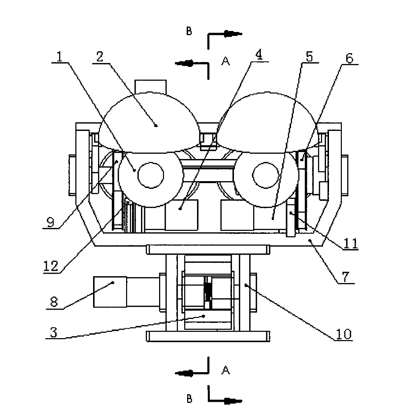
[0019] Embodiment one: see figure 1 , the double-sided robot head device includes an eye support frame 7, a mouth mounting frame 10, a four-eye horizontally rotating part 1, a four-eyelid part 2, a double-mouth part 3, and three micromotors—— A micro-motor one 4, a micro-motor two 5 and a micro-motor three 8, two synchronous belt transmission assemblies-a synchronous belt transmission assembly one 6 and a synchronous belt transmission assembly two 9; it is characterized in that the eye support frame 7 Fixedly connect the mouth installation frame 10 below, micromotor one 4 and micromotor two 5 are fixedly installed on the eye support frame 7, four eyeball horizontal rotating parts 1 are installed on the eye support frame 7, synchronous belt drive assembly two 9 and The four eyeball horizontally rotating parts 1 are connected, and the micro motor one 4 is driven by the synchronous belt transmission assembly two 9 to drive the four eyeball horizontally rotating part 1; the four e...
Embodiment 2
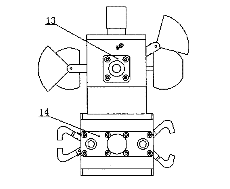
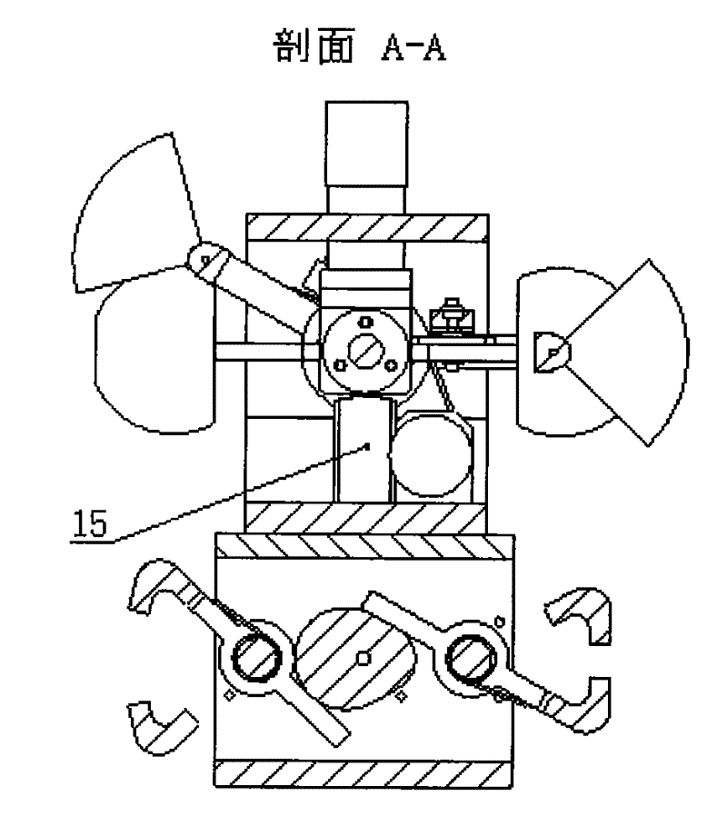
[0020] Embodiment 2: This embodiment is the same as Embodiment 1, and the special features are as follows: see figure 1 and figure 2 The two ends of the four-eye horizontally rotating part 1 are equipped with positioning sleeves and miniature bearings, the four-eyelid part 2 is installed on the four-eye horizontally rotating part 1, and axially positioned by the positioning sleeve, the four-eye horizontally rotating part 1 is set The two ends of the miniature bearings are supported through the through holes at both ends of the eye support frame 7, and two eye bearing end caps 13 are fixedly connected to the two sides of the eye support frame 7 for axial positioning; the micro motor two 5 and a The motor mounting plate one 11 is fixedly connected, the motor mounting plate one 11 is fixedly connected with the eye support frame 7; the micro motor one 4 is fixedly connected with a motor mounting plate two 12, and the motor mounting plate two 12 is fixedly connected with the eye s...
PUM
 Abstract
Description
Claims
Application Information
 - Generate Ideas
- Intellectual Property
- Life Sciences
- Materials
- Tech Scout
- Unparalleled Data Quality
- Higher Quality Content
- 60% Fewer Hallucinations
Browse by: Latest US Patents, China's latest patents, Technical Efficacy Thesaurus, Application Domain, Technology Topic, Popular Technical Reports.
© 2025 PatSnap. All rights reserved.Legal|Privacy policy|Modern Slavery Act Transparency Statement|Sitemap|About US| Contact US: help@patsnap.com


