Wood board cutting equipment for furniture production
A technology for cutting equipment and boards, applied in sawing equipment, sawing components, manufacturing tools, etc., can solve problems such as low efficiency, time-consuming and laborious
- Summary
- Abstract
- Description
- Claims
- Application Information
AI Technical Summary
Problems solved by technology
Method used
Image
Examples
Embodiment 1
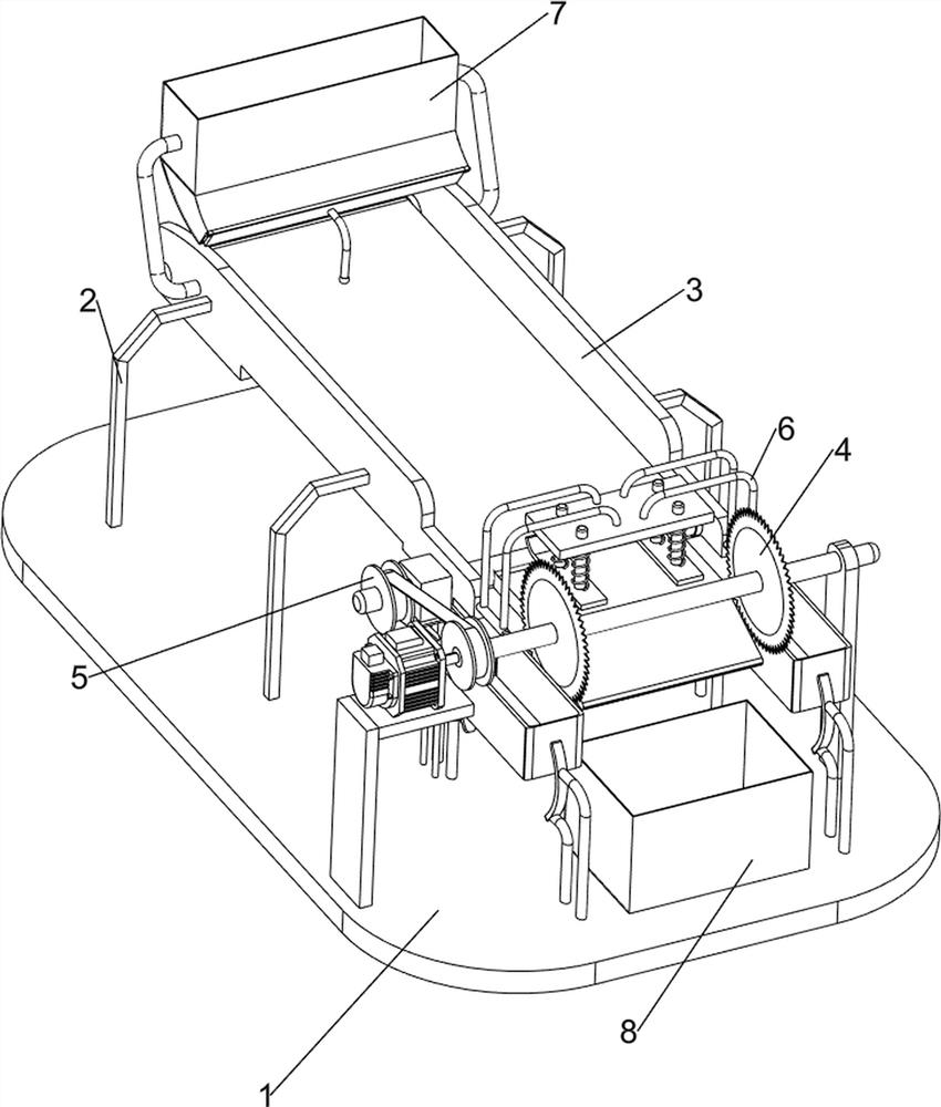
[0028] A device for cutting boards for furniture production, such as Figure 1-3 As shown, it includes a bottom plate 1, legs 2, a first baffle plate 3, a cutting mechanism 4 and a transmission mechanism 5. Two legs 2 are connected to the left and right sides of the rear of the bottom plate 1, and the legs 2 on the left and right sides A first baffle 3 is connected between them, a cutting mechanism 4 is connected to the top front side of the bottom plate 1, and a transmission mechanism 5 is connected between the first baffles 3 on both sides.
[0029] The cutting mechanism 4 includes a support plate 41, a motor frame 42, a high-speed response motor 43, a rotating shaft 44 and a saw blade 45; A high-speed response motor 43 is installed on the frame 42 top, and the supporting plate 41 top is rotatably connected with a rotating shaft 44.
[0030] The transmission mechanism 5 includes a transmission shaft 51, a transmission wheel 52, a belt 53, a first bracket 54, a gearbox 55 an...
Embodiment 2
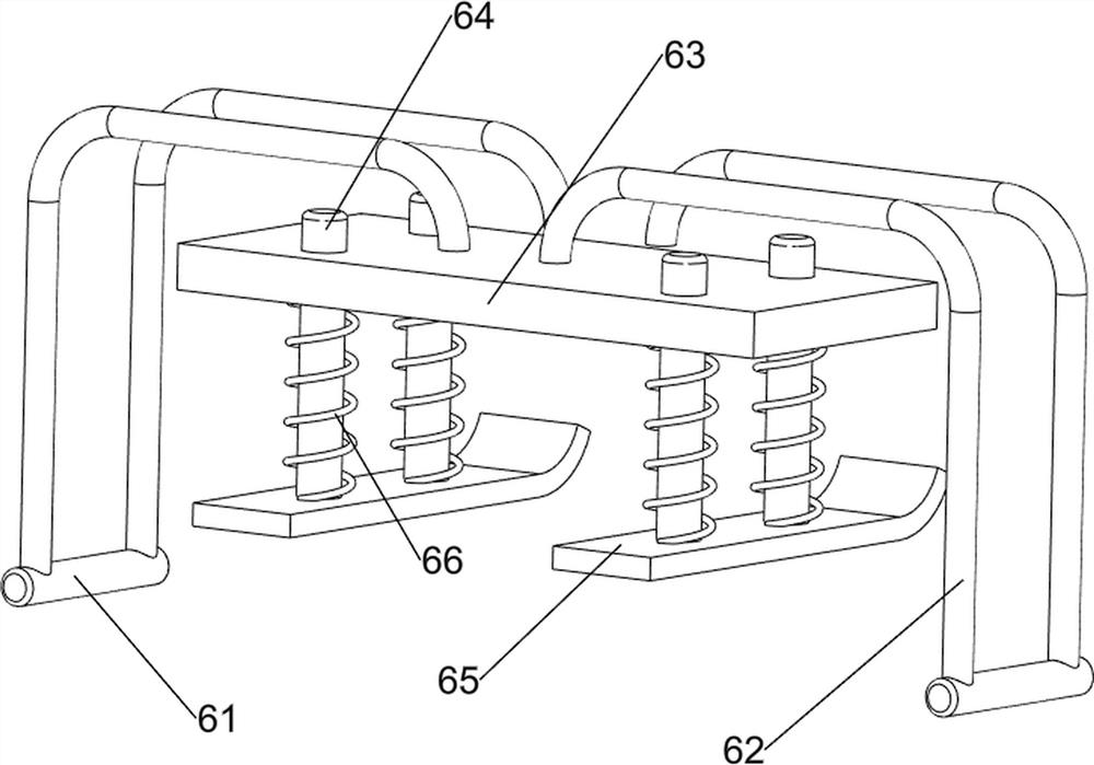
[0033] On the basis of Example 1, such as Figure 4 Shown, also include hold-down mechanism 6, hold-down mechanism 6 includes support tube 61, fixed frame 62, support block 63, slide bar 64, press plate 65 and spring 66, the first baffle plate 3 front sides of both sides are all Connected with support tube 61, both sides of the support tube 61 tops are connected with fixed frame 62, between the fixed frame 62 inner upper part on both sides is connected with support block 63, all left and right sides of support block 63 are slidingly connected with two sliders. A pressing plate 65 is connected between the bar 64 and the sliding bars 64 on both sides. The pressing plate 65 is located directly in front of the conveyor belt 56 . A spring 66 is sleeved between the pressing plate 65 and the supporting block 63 .
[0034] When the plank is transported forward, the plank moves forward and contacts the pressing plate 65 to make it move upwards, the springs 66 on both sides of the press...
Embodiment 3
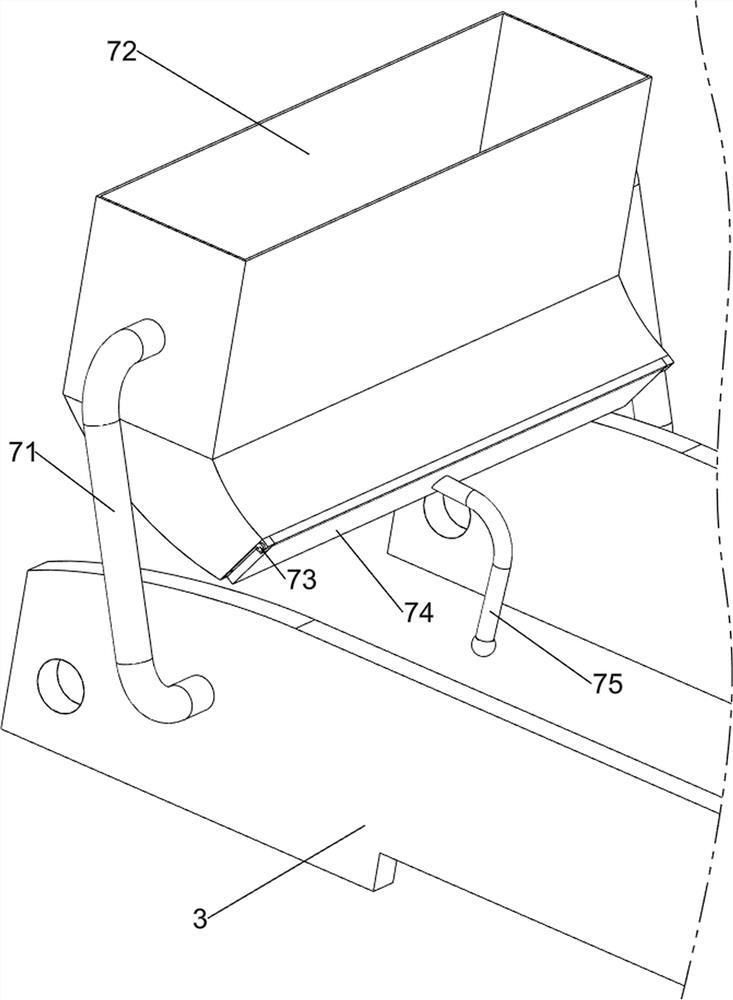
[0036] On the basis of Example 2, such as Figure 5 As shown, it also includes a blanking mechanism 7. The blanking mechanism 7 includes a support rod 71, a blanking box 72, a rotating rod 73, a second baffle 74 and a pull bar 75, and the first baffle 3 rear outsides on both sides Both are connected with support rods 71, and the upper parts of the support rods 71 on both sides are connected with a lower material box 72, and the right side of the lower material box 72 is rotationally connected with a rotating rod 73, and the lower part of the rotating rod 73 is connected with a second baffle plate 74, A tie rod 75 is connected in the middle of the right side of the second baffle plate 74 .
[0037] When the planks need to be cut, a large number of planks are manually placed in the blanking box 72, and then they are unloaded by manually controlling the pull rod 75, so that there is no need to manually place the planks on the conveyor belt 56, which saves manpower and improves ...
PUM
 Abstract
Description
Claims
Application Information
 - R&D Engineer
- R&D Manager
- IP Professional
- Industry Leading Data Capabilities
- Powerful AI technology
- Patent DNA Extraction
Browse by: Latest US Patents, China's latest patents, Technical Efficacy Thesaurus, Application Domain, Technology Topic, Popular Technical Reports.
© 2024 PatSnap. All rights reserved.Legal|Privacy policy|Modern Slavery Act Transparency Statement|Sitemap|About US| Contact US: help@patsnap.com


