
Intelligent surface MISO system joint beam forming method based on successive approximation

A successive approximation and beamforming technology, which is applied in the transmission system, signal transmission system, electrical signal transmission system, etc., can solve the problem of not considering the interaction of adjacent cells

Active Publication Date: 2021-05-14
QILU UNIV OF TECH
View PDF6 Cites 0 Cited by
  • Summary
  • Abstract
  • Description
  • Claims
  • Application Information

AI Technical Summary

Problems solved by technology

[0004] Most previous works focus on single-cell scenarios, without considering the interaction between adjacent cells

Method used


Image

  • Intelligent surface MISO system joint beam forming method based on successive approximation
  • Intelligent surface MISO system joint beam forming method based on successive approximation
  • Intelligent surface MISO system joint beam forming method based on successive approximation

Examples


Embodiment

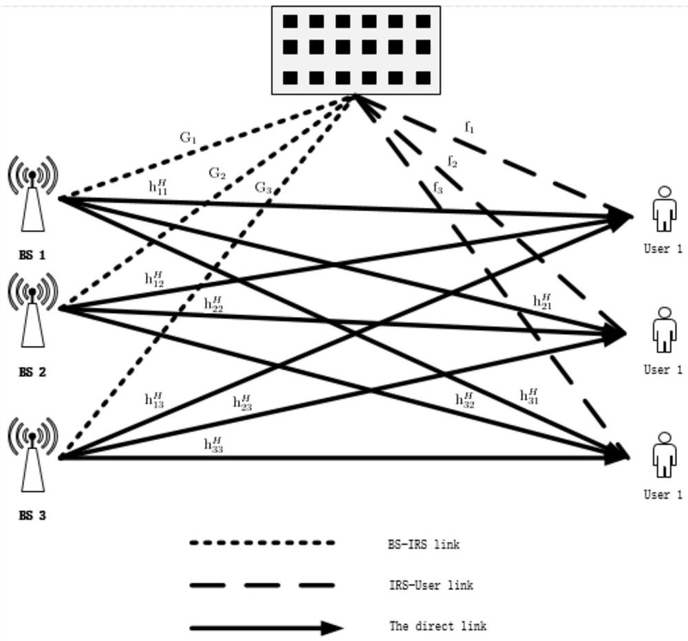
[0199] A multi-cell MISO system assisted by IRS, where IRS is deployed to assist multi-cell communication and suppress inter-cell interference, as figure 1 shown. We assume K transmitters equipped with multiple antennas communicating with their intended single-antenna receivers. Assume that the number of antennas at each BS is M, and the number of reflection units at the IRS is N. make represents the set of BSs or users in the system, Represents the collection of reflection units at the IRS. make Denotes the channel matrix from BS j to IRS, Denotes the channel vector from IRS to user k, h k,j Indicates from BS j channel vector to user k. The transmitter of each user k transmits its respective information signal s k sent to its designated receiver. In order to suppress the interference between cells, the signal is formed by the beamforming vector precoded. The transmitted signal of each base station k is denoted as x k =w k the s k . Suppose each BS k has a...


PUM


Abstract

The invention discloses an intelligent surface MISO system joint beam forming method based on successive approximation, belongs to the technical field of multi-cell multi-user MIMO communication, and aims to solve the technical problem of how to effectively realize joint beam forming of the system. According to the method, the sum rate of all users in the MISO system is maximized based on an AO frame and a successive approximation method by jointly optimizing a transmission beam forming vector wk of the BS and a reflection beam forming vector theta of the IRS under the condition that the single transmitting power constraint of the BS and the reflection constraint of the IRS are met.

Description

technical field [0001] The invention relates to the technical field of multi-cell and multi-user MIMO communication, in particular to an intelligent surface MISO system joint beamforming method based on successive approximation. Background technique [0002] With the development of emerging applications such as the Internet of Things and artificial intelligence, the fifth generation (5G) and beyond cellular networks have created a demand for a large number of wireless devices with various quality of service (QoS). High data transfer rate, low latency, high energy efficiency, low cost, increased system capacity and large-scale device connectivity are crucial to future communication systems. [0003] To achieve the performance of upcoming communication networks, many wireless communication technologies have been proposed and intensively studied, including ultra-dense networking (UDN), massive multiple-input multiple-output (MIMO), and millimeter wave (mmWave) communication. A...

Claims


Application Information

Patent Timeline
Patent Type & Authority Applications(China)
IPC IPC(8): H04B7/06H03M1/38
CPCH04B7/0617H03M1/38H04B7/04013
Inventor 董安明邱静禹继国韩玉冰李素芳梁风
Owner QILU UNIV OF TECH
Learn More