Vacuum tank
A vacuum tank and vacuum heat insulation technology, which is applied in the direction of tank trucks, packaging, large containers, etc., can solve problems such as large pressure on the shell, air leakage in the vacuum heat insulation cavity, deformation of the vacuum tank, etc.
- Summary
- Abstract
- Description
- Claims
- Application Information
AI Technical Summary
Problems solved by technology
Method used
Image
Examples
Embodiment 1
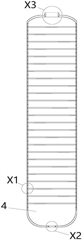
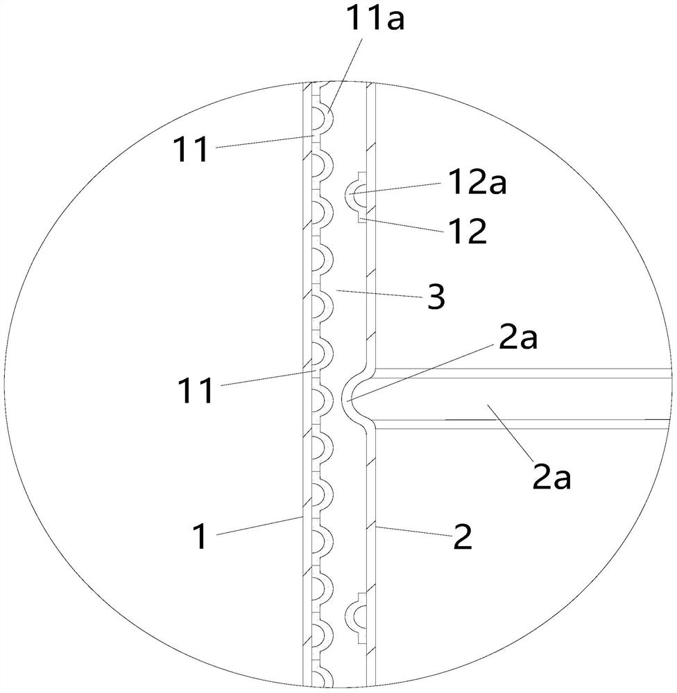
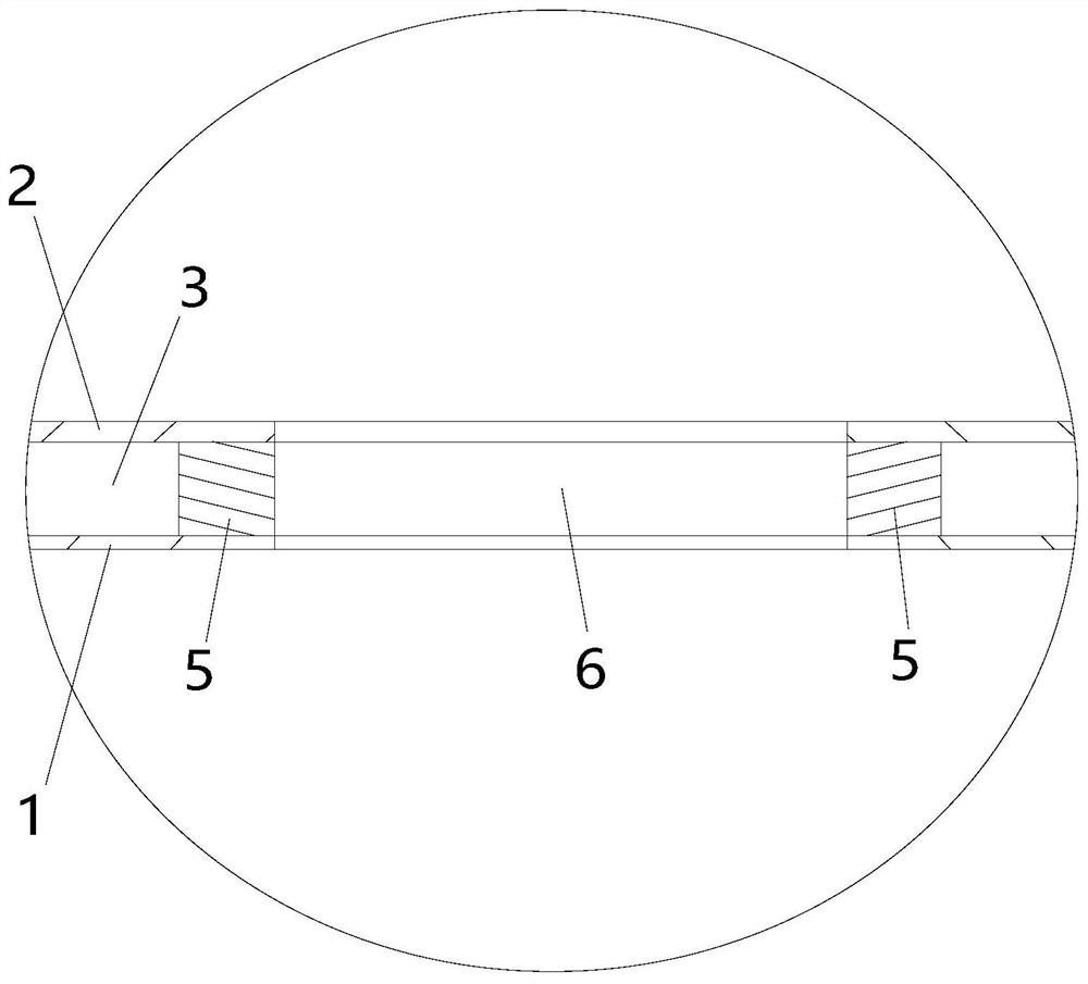
[0116] Figure 1 to Figure 6A specific embodiment of the vacuum tank of the present application is shown, the vacuum tank is a water tank for storing water, which includes some traditional vacuum tanks: an outer shell 1, an inner shell 2 arranged in the outer shell, forming The tank cavity 4 inside the inner shell, and the vacuum heat insulation cavity 3 formed between the outer shell and the inner shell. Both the outer shell 1 and the inner shell 2 are made of stainless steel.
[0117] If the inner shell 2 of the vacuum tank is suspended in the outer shell 1 as in the traditional solution, when the volume of the tank cavity is large and stores tens of tons or even hundreds of tons of water, the inner shell 2 is easy to fall and deform under the action of water gravity , and a large area of close contact with the outer shell 1, so that the heat is quickly transferred between the inner shell and the outer shell, reducing the thermal insulation of the tank. Moreover, the fal...
Embodiment 2
[0148] Figure 7 to Figure 10It shows the second specific embodiment of the vacuum tank of the present application. The structure of the vacuum tank is similar to the structure of the vacuum tank in the first embodiment, the main difference is that: in this embodiment, the shell wall of the inner shell 2 and Deformation folds for absorbing / releasing deformation are not provided, but ring-shaped deformation folds surrounding the periphery of the inner shell 2 are integrally provided on the shell wall of the outer shell 1 . In order to illustrate the technical solution, the deformed folds on the shell 1 are now referred to as shell deformed folds 1a.
[0149] When the temperature of the outer shell 1 rises, the outer shell deformation folds 1a on the shell wall shrink to absorb the expansion deformation of the outer shell, thereby preventing the expansion stress of the outer shell from concentrating on the connection between the inner shell and the outer shell, causing deformati...
Embodiment 3
[0159] Figure 11 to Figure 14 It shows the third specific embodiment of the vacuum tank of the present application. The structure of the vacuum tank is similar to that of the vacuum tank in Embodiment 1 and Embodiment 2. The main difference is that not only the inner shell 2 is integrally arranged on the shell wall Annular deformation folds 2a surrounding the periphery of the tank chamber 4 are provided, and ring-shaped deformation folds 1a surrounding the periphery of the inner shell 1 are integrally provided on the shell wall of the outer shell 1 . That is, deformation folds are provided on both the shell wall of the inner shell 2 and the shell wall of the outer shell 1 .
[0160] The vacuum tank of this embodiment is very suitable for such a situation: both ends of the vacuum tank are fixed, and the heights of the inner shell and the outer shell are limited and fixed. For example, the two ends of the vacuum tank are fastened to the outer support frame.
PUM
 Abstract
Description
Claims
Application Information
 - R&D
- Intellectual Property
- Life Sciences
- Materials
- Tech Scout
- Unparalleled Data Quality
- Higher Quality Content
- 60% Fewer Hallucinations
Browse by: Latest US Patents, China's latest patents, Technical Efficacy Thesaurus, Application Domain, Technology Topic, Popular Technical Reports.
© 2025 PatSnap. All rights reserved.Legal|Privacy policy|Modern Slavery Act Transparency Statement|Sitemap|About US| Contact US: help@patsnap.com


