
Lifting pin elastic limiting mechanism of slewing mechanism

A technology of elastic limit and slewing mechanism, which is applied in workpiece clamping devices, manufacturing tools, etc., can solve problems such as inability to achieve accurate positioning, and damage to the hands of debuggers

Pending Publication Date: 2021-05-14
TIANJIN MOTOR DIES
View PDF0 Cites 0 Cited by
  • Summary
  • Abstract
  • Description
  • Claims
  • Application Information

AI Technical Summary

Problems solved by technology

[0003] 1. When the debugger rotates the rotary body to reach the retreat and reset state, it cannot achieve accurate positioning
[0004] 2. When the debugger is operating, the rotator will rotate by itself under the action of the center of gravity, and there is a risk of hurting the debugger's hand

Method used


Image

  • Lifting pin elastic limiting mechanism of slewing mechanism
  • Lifting pin elastic limiting mechanism of slewing mechanism
  • Lifting pin elastic limiting mechanism of slewing mechanism

Examples


Embodiment Construction

[0023] It should be noted that, in the case of no conflict, the embodiments of the present invention and the features in the embodiments can be combined with each other.

[0024] In describing the present invention, it should be understood that the terms "center", "longitudinal", "transverse", "upper", "lower", "front", "rear", "left", "right", " The orientations or positional relationships indicated by "vertical", "horizontal", "top", "bottom", "inner" and "outer" are based on the orientations or positional relationships shown in the drawings, and are only for the convenience of describing the present invention and Simplified descriptions, rather than indicating or implying that the device or element referred to must have a particular orientation, be constructed and operate in a particular orientation, and thus should not be construed as limiting the invention. In addition, the terms "first", "second", etc. are used for descriptive purposes only, and should not be understood ...


PUM


Abstract

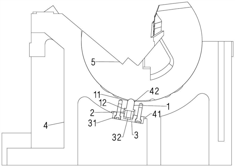
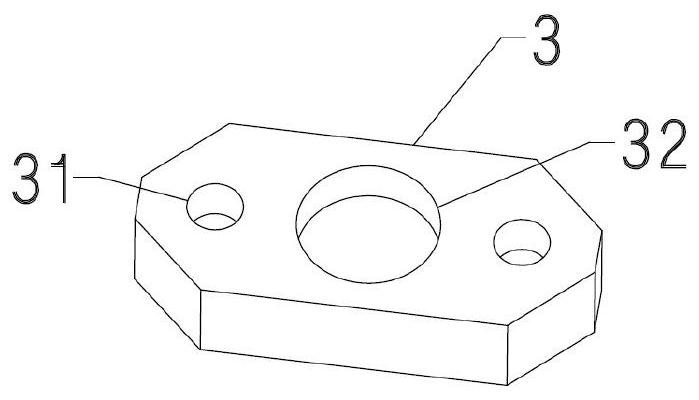
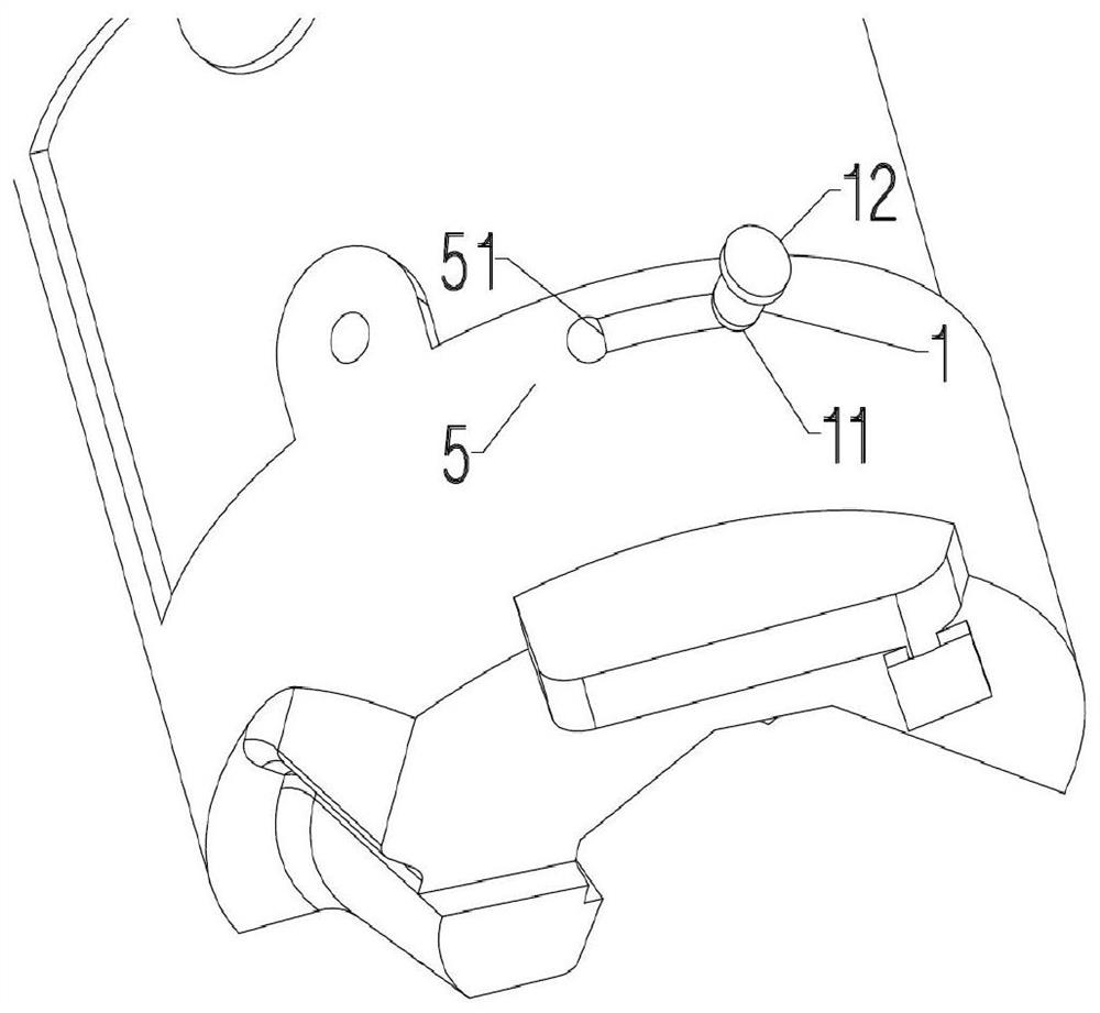
The invention provides a lifting pin elastic limiting mechanism of a slewing mechanism. The mechanism comprises a lifting pin, a spring and a mounting plate, wherein the spring is a rectangular spiral spring, the lifting pin is connected with one end of the spring, the other end of the spring is connected with the mounting plate, the lifting pin comprises a lifting pin spherical front end and a lifting pin step, and the lifting pin step is connected with the bottom of the lifting pin spherical front end. The mounting plate comprises screw holes and a mounting plate center groove, the mounting plate center groove is located in the center of the mounting plate, and the screw holes are located in the two sides of the mounting plate. According to the lifting pin elastic limiting mechanism of the slewing mechanism, although the lifting pin elastic limiting mechanism is simple in structural form, the lifting pin elastic limiting mechanism has practicability, and the cost of components is low.

Description

technical field [0001] The invention belongs to the field of mold processing, and in particular relates to an elastic limiting mechanism for a push pin of a rotary mechanism. Background technique [0002] At present, in the mold production of automobiles, in order to meet the diversity of parts, it is often necessary to use some special mechanisms to meet the forming requirements of the parts, among which the rotary mechanism is widely used. Due to the particularity of the slewing mechanism, the slewing body can rotate in the slewing body seat. In practical applications, the workshop commissioning personnel often need to turn the slewing body to reach the two states of retraction and reset, so in this Several issues arise during the process: [0003] 1. When the debugger rotates the rotary body to reach the retreat and reset state, it cannot achieve accurate positioning. [0004] 2. When the debugger is operating, the revolving body will rotate by itself under the action o...

Claims


Application Information

Patent Timeline
Patent Type & Authority Applications(China)
IPC IPC(8): B25B11/00
CPCB25B11/00
Inventor 金晶
Owner TIANJIN MOTOR DIES
Learn More