
Insulation type electromagnetic relay capable of automatically detecting coil

An electromagnetic relay and coil insulation technology, applied in the direction of electromagnetic relay, electromagnetic relay details, relays, etc., can solve problems affecting the normal operation of the relay, damage to the relay, short circuit between the input circuit and the output circuit of the relay, etc.

Pending Publication Date: 2021-05-11
SANYOU CORP LTD
View PDF0 Cites 3 Cited by
  • Summary
  • Abstract
  • Description
  • Claims
  • Application Information

AI Technical Summary

Problems solved by technology

In the actual use of existing relays, they often encounter instantaneous high voltage situations. At this time, the current in the relay is very large and the voltage is high. If the insulation performance and electric strength of the relay are insufficient, the input circuit in the relay will be damaged. Short circuit with the output circuit, causing damage to the relay. At the same time, the existing relays are increasingly miniaturized and refined. Affected by factors such as structure, shape, function, production process and cost, the distance between the internal circuit components is small. If only Relying on air insulation, it is difficult to meet its requirements for insulation performance and electric strength, which will affect the normal operation of the relay to a certain extent and cause great safety hazards

Method used


Image

  • Insulation type electromagnetic relay capable of automatically detecting coil
  • Insulation type electromagnetic relay capable of automatically detecting coil
  • Insulation type electromagnetic relay capable of automatically detecting coil

Examples


Embodiment Construction

[0045]The present invention will be described in detail below in conjunction with the accompanying drawings.

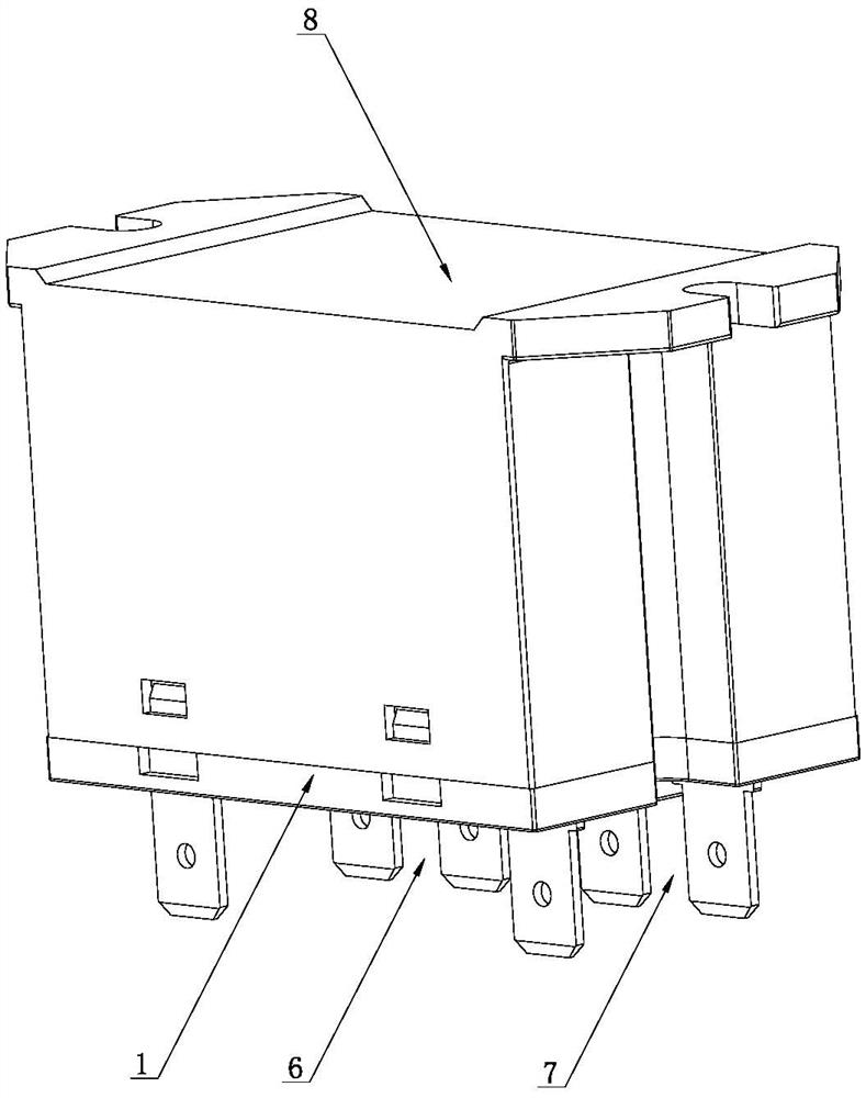
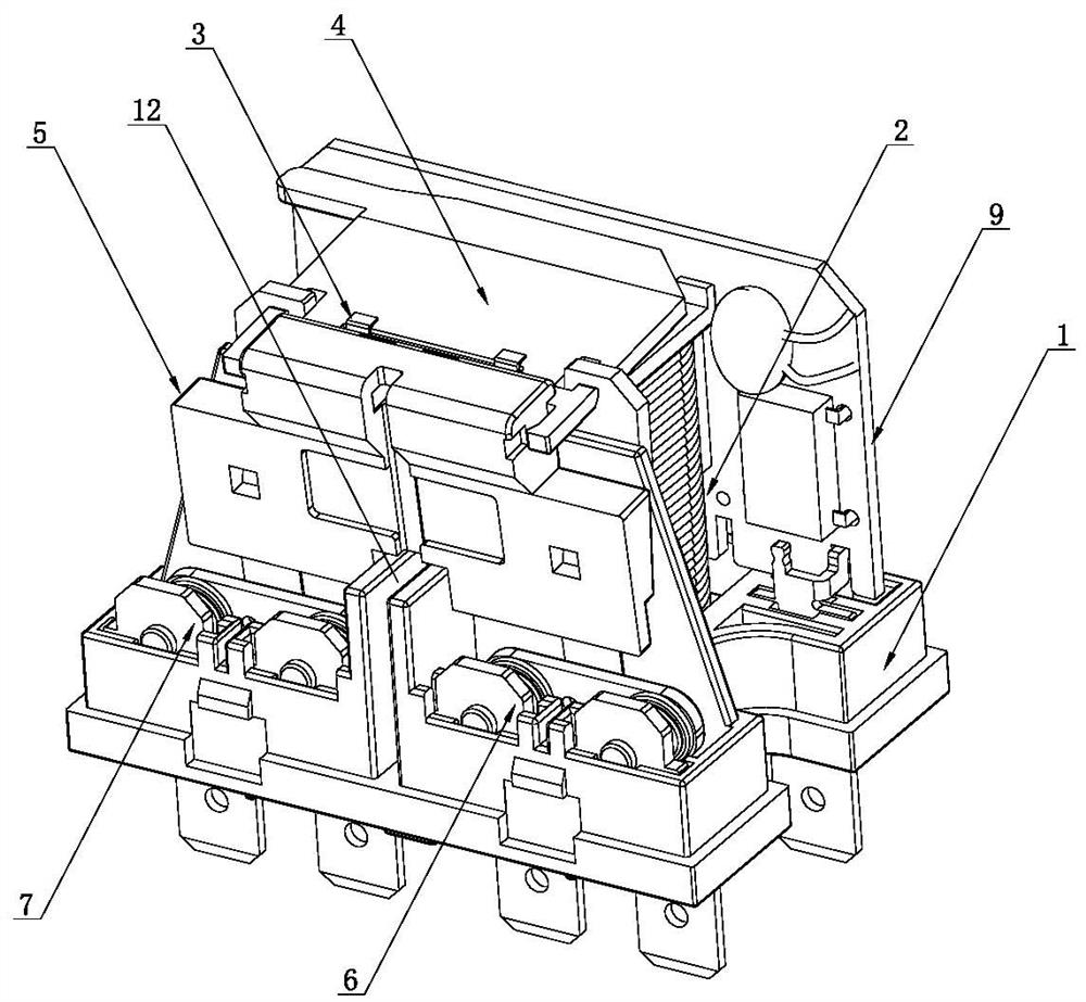
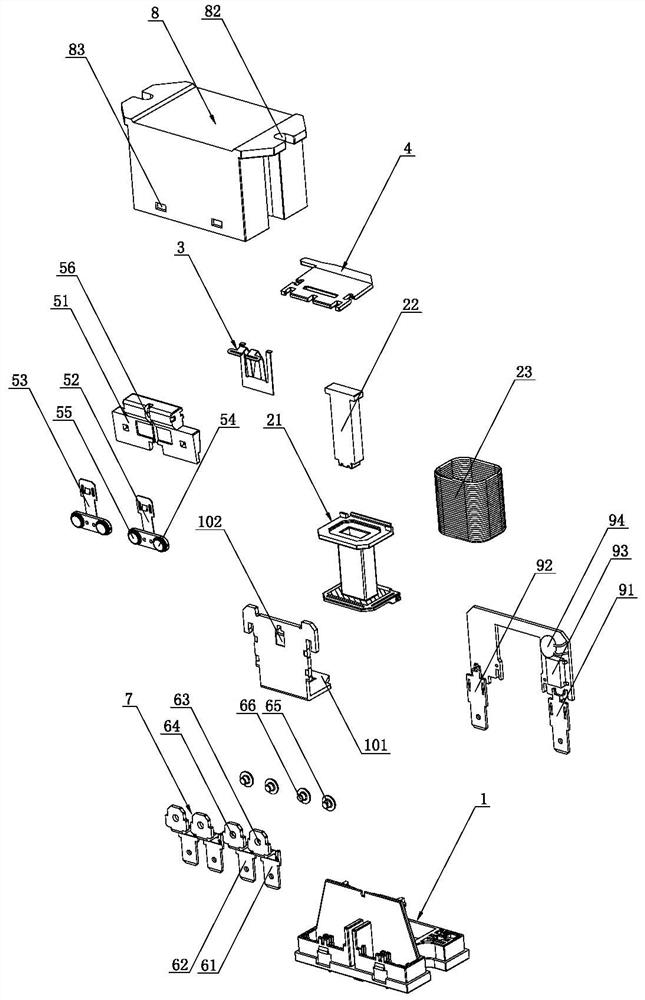
[0046] Such as Figure 1 to Figure 6 As shown, an automatic detection coil insulation type electromagnetic relay of the present invention includes a base 1, an electromagnetic coil 2 installed on the base 1 and a reset shrapnel 3, and the base 1 is rotated near the top of the electromagnetic coil 2. The armature 4, the electromagnetic coil 2 is used to drive the armature 4 to rotate, the reset spring 3 is used to drive the armature 4 to return to its original position, one end of the armature 4 is provided with a contact assembly 5, and the base 1 is provided with a barrier Plate 11, the baffle plate 11 is used to block and separate the electromagnetic coil 2 and the contact assembly 5, the baffle plate 11 is provided with a channel baffle 12, the baffle plate 11 is vertically arranged with the channel baffle 12, the A plurality of partitions 13 are arranged in the b...


PUM


Abstract

The invention relates to the technical field of relays, and concretely relates to an insulation type electromagnetic relay capable of automatically detecting a coil. The relay comprises a base, an electromagnetic coil and a reset elastic piece, the electromagnetic coil and the reset elastic piece are arranged on the base, an armature is rotationally arranged on the base close to the top of the electromagnetic coil, the electromagnetic coil is used for driving the armature to rotate, and the reset elastic piece is used for driving the armature to return to the original position. One end of the armature is provided with a contact assembly, the base is provided with a baffle, the baffle is provided with a channel baffle, the base is internally provided with a plurality of baffles, the plurality of baffles divide the internal space of the base into a plurality of compartments, the plurality of compartments are provided with a first terminal set and a second terminal set, and an insulation gap is arranged between two adjacent baffles. The electromagnetic coil drives the contact assembly to be connected with or disconnected from the first terminal set and the second terminal set by attracting or repelling the armature, a shell is arranged outside the base, the electromagnetic coil comprises a framework, an iron core is arranged in the framework, a coil is arranged outside the framework, and the base, the shell and the framework are all made of insulating flame-retardant plastic.

Description

technical field [0001] The invention relates to the technical field of relays, in particular to an automatic detection coil insulation type electromagnetic relay. Background technique [0002] Electromagnetic relay is an electronic control device, which has a control system (also known as input circuit) and a controlled system (also known as output circuit), usually used in automatic control circuits, it actually uses low voltage and weak current circuits On and off, to control a kind of "automatic switch" of high voltage and strong current, so it plays the role of automatic adjustment, safety protection, conversion circuit and so on in the circuit. In the actual use of existing relays, they often encounter instantaneous high voltage situations. At this time, the current in the relay is very large and the voltage is high. If the insulation performance and electric strength of the relay are insufficient, the input circuit in the relay will be damaged. Short circuit with the ...

Claims


Application Information

Patent Timeline
IPC IPC(8): H01H50/14H01H50/02
CPCH01H50/02H01H50/14
Inventor 刘振伟
Owner SANYOU CORP LTD
Learn More