
Low dropout regulator based on sub-threshold region

A low-dropout voltage regulator, low-dropout technology, applied in instruments, regulating electrical variables, control/regulation systems, etc., can solve problems such as difficult control, achieve the effect of stable operation and reduce current mismatch

Active Publication Date: 2021-05-11
HIMAX TECH LTD
View PDF17 Cites 0 Cited by
  • Summary
  • Abstract
  • Description
  • Claims
  • Application Information

AI Technical Summary

Problems solved by technology

However, the sub-threshold region is not easy to control due to current mismatch in process variation

Method used


Image

  • Low dropout regulator based on sub-threshold region
  • Low dropout regulator based on sub-threshold region

Examples


Embodiment Construction

[0027] As used throughout the specification of this application, including the claims, the term "coupled (or connected)" may refer to any means of connection, direct or indirect. For example, if it is described that a first device is coupled (or connected) to a second device, it should be interpreted that the first device can be directly connected to the second device, or the first device can be connected to the second device through other devices or certain A connection means indirectly connected to the second device. Terms such as "first" and "second" mentioned in the entire specification of this application (including the claims) are used to name components (elements), or to distinguish different embodiments or ranges, and are not used to limit The upper or lower limit of the number of components is not used to limit the order of the components. In addition, wherever possible, components / members / steps using the same reference numerals in the drawings and the detailed descr...


PUM


Abstract

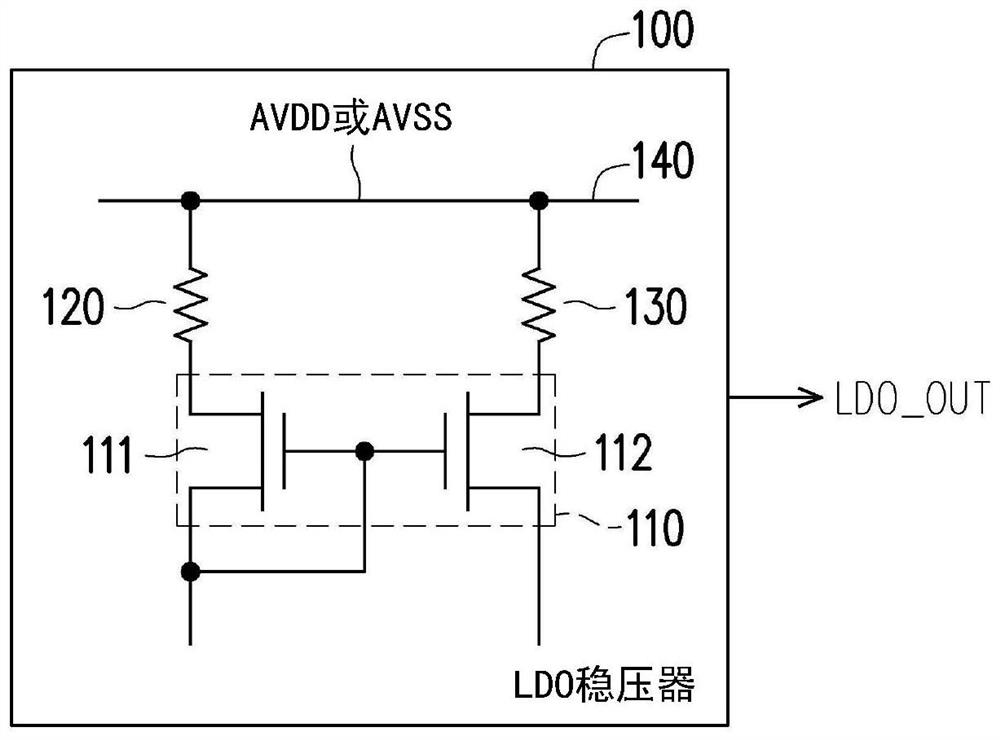
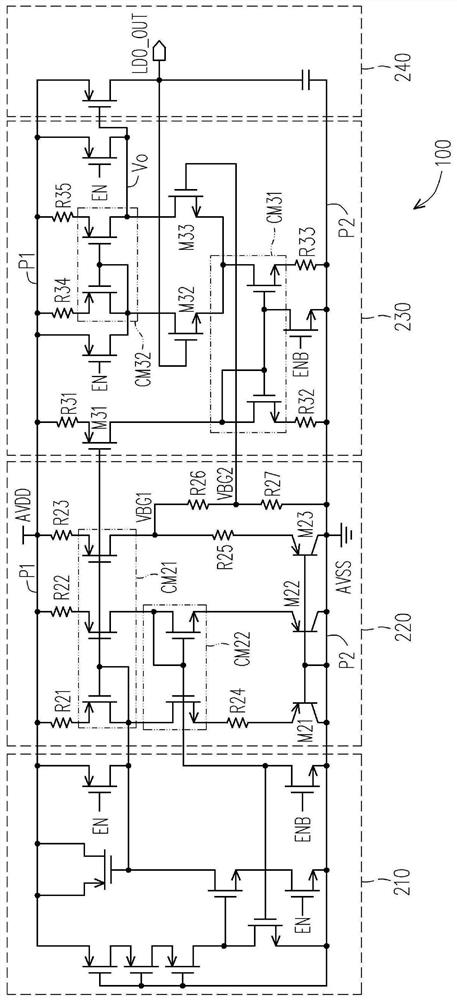
A low dropout regulator is configured to generate a low dropout voltage. The low dropout regulator includes at least one current mirror and at least one resistor. The at least one current mirror operates in a sub-threshold region. A first end of the at least one resistor is directly coupled to the at least one current mirror. The second end of the at least one resistor is directly coupled to the power line.

Description

【Technical field】 [0001] The present invention relates to a voltage generating circuit, and in particular to a low dropout (LDO) regulator based on a subthreshold region. 【Background technique】 [0002] A low dropout regulator (LDO regulator) is a common power management circuit used to regulate a stable voltage source (ie, independent of output load, input voltage, and temperature). A basic LDO regulator includes a bandgap voltage generator, an error amplifier, and a power transistor. In order to achieve ultra-low quiescent current (ultra-low quiescent current), sub-threshold (sub-threshold) technology is applied to low dropout regulators. However, the sub-threshold region is not easy to control due to current mismatch in process variation. [0003] It should be noted that the content in the paragraph "Background Art" is used to help the understanding of the present invention. Some (or all) of the content disclosed in the "Background" paragraph may not be known technolog...

Claims


Application Information

Patent Timeline
Patent Type & Authority Applications(China)
IPC IPC(8): G05F3/26
CPCG05F3/262
Inventor 刘宇轩
Owner HIMAX TECH LTD
Learn More