
Intelligent visual monitoring device based on Internet of Things

A monitoring device and Internet of Things technology, which is applied in the direction of electromechanical devices, TVs, color TVs, etc., can solve the problems of troublesome camera angle adjustment and danger, and achieve the effect of reducing labor intensity

Pending Publication Date: 2021-05-11
广东聚晨晋力通信设备科技有限公司
View PDF0 Cites 6 Cited by
  • Summary
  • Abstract
  • Description
  • Claims
  • Application Information

AI Technical Summary

Problems solved by technology

[0005] To this end, the present invention provides an intelligent visual monitoring device based on the Internet of Things. By turning the knob, the eighth rotating shaft can be driven to rotate, and the eighth rotating shaft can drive the two rotating shafts to rotate seven times. When the knob is turned clockwise, only one of the rotating shafts can be threaded The rod rotates, and when the knob is turned counterclockwise, the other threaded rod can be rotated, so that the moving distance of the two threaded blocks can be adjusted, and the horizontal position of the camera can be changed. After the camera is installed, the camera can also be adjusted. The horizontal position is more convenient when adjusting the angle of the camera, so as to solve the problem that a lot of dust will accumulate on the surface of the existing camera during use, and these dusts need to be manually cleaned regularly, and the manual cleaning is due to the influence of the installation environment of the camera Manual cleaning is more troublesome, and there may be dangers. It is more troublesome to adjust the angle of the camera after the camera is installed.

Method used


Image

  • Intelligent visual monitoring device based on Internet of Things
  • Intelligent visual monitoring device based on Internet of Things
  • Intelligent visual monitoring device based on Internet of Things

Examples


Embodiment 1

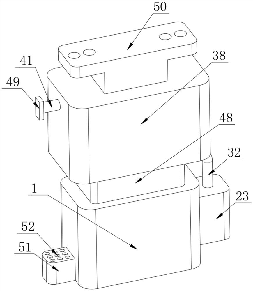
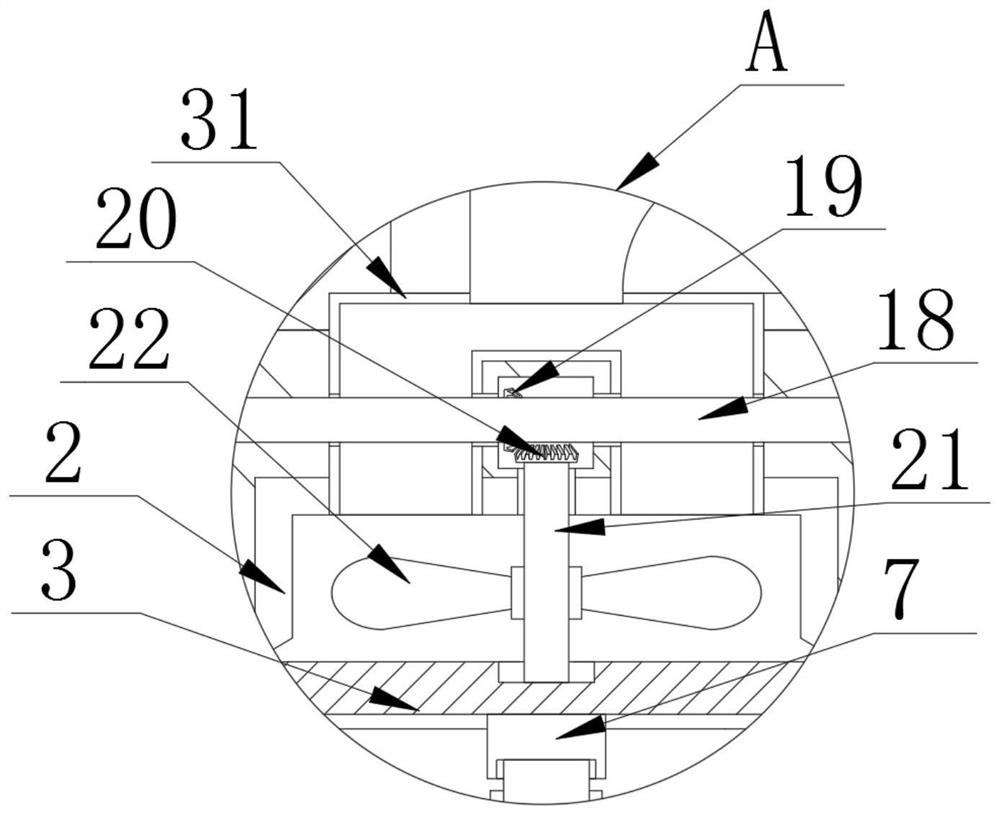
[0028] Embodiment 1, with reference to attached Figure 1-7, an intelligent visual monitoring device based on the Internet of Things provided by the present invention includes a housing 1, and the top of the housing 1 is provided with a cavity 1, a cavity 2 and a cavity 3, and the cavity 2 is located between the cavity 1 and the cavity 1. On the inner side of cavity three, an air cylinder 2 is embedded in the top inner wall of the housing 1, and the air cylinder 2 is located at the bottom of the cavity two, and a fixed rod 3 is fixedly embedded inside the air cylinder 2, and a cleaning mechanism, an adjustment mechanism is provided on the outside of the top of the housing 1;

[0029] The fixing mechanism includes a motor 4, and the motor 4 is fixedly installed on one side of the housing 1. A protective assembly is provided outside the motor 4. Two fixing posts 5 are fixedly connected to the inner wall of the bottom of the housing 1. The housing 1 is The side inner wall is fix...

Embodiment 2

[0037] Embodiment 2, with reference to attached Figure 8 The present invention provides an intelligent visual monitoring device based on the Internet of Things. The difference from Embodiment 1 is that the protective assembly includes a protective shell 51, and the protective shell 51 is fixedly connected to one side of the shell 1. The protective shell 51 is sleeved on the outside of the motor 4 , and the top and bottom of the protective shell 51 are fixedly embedded with cooling nets 53 .

[0038] The use process of the present invention is as follows: when you need to clean the dust on the surface of the protective cover 9, connect the power supply of the motor 4, the rotation of the motor 4 drives the rotation of the rotating shaft 12, the rotation of the rotating shaft 12 drives the rotation of the bevel gear 13, and the rotation of the bevel gear 1 13 rotation drives bevel gear 2 14 rotation, bevel gear 2 14 rotation drives shaft 2 15 rotation, shaft 2 15 rotation drive...


PUM


Abstract

The invention discloses an intelligent visual monitoring device based on the Internet of Things, which comprises a shell; a cavity I, a cavity II and a cavity III are arranged at the top of the shell; the cavity II is located on the inner sides of the cavity I and the cavity III; an air duct is embedded in the inner wall of the top of the shell and located at the bottom of the cavity II; a fixed rod is fixedly embedded in the air duct; a cleaning mechanism is arranged in the shell; an adjusting mechanism is arranged on the outer side of the top of the shell; and a fixing mechanism comprises a motor, and the motor is fixedly installed on one side of the shell. The intelligent visual monitoring device based on the Internet of Things provided by the invention has the beneficial effects that dust on the surface of a protective cover is cleaned, the rotation of the motor can also make a connecting rod rotate, the dust on the surface of the protective cover can be efficiently cleaned by rotating the protective cover and matching the protective cover with a cleaning brush, so that the dust cannot be accumulated on the surface of the protective cover to influence the shooting picture of a camera, the dust on the surface does not need to be manually and regularly cleaned, and the labor intensity of people can be reduced.

Description

technical field [0001] The invention relates to the technical field of monitoring, in particular to an intelligent visual monitoring device based on the Internet of Things. Background technique [0002] The surveillance camera can convert the analog video signal generated by the video capture device into a digital signal, and then store it in the computer. The video signal captured by the analog camera must be converted to a digital mode by a specific video capture card and compressed before it can be converted to a computer for use. The monitoring camera can directly capture the image, and then transmit it to the computer through a serial, parallel port or USB interface. The cameras in the computer market are basically surveillance cameras, and among the surveillance cameras are USB surveillance cameras using new data transmission interfaces. Most of the products that can be seen on the market are such products. [0003] There are following deficiencies in the prior art: ...

Claims


Application Information

Patent Timeline
Patent Type & Authority Applications(China)
IPC IPC(8): F16M11/08F16M11/18H02K5/20H04N5/225B08B1/00B08B1/04
CPCF16M11/08F16M11/18H02K5/20H04N23/51B08B1/12B08B1/32
Inventor 郑嘉欣
Owner 广东聚晨晋力通信设备科技有限公司
Learn More