Anti-collision monitoring equipment

A monitoring equipment and anti-collision technology, applied in the direction of mechanical equipment, color TV parts, TV system parts, etc., can solve the problems of dangerous personal safety, waste of manpower, easy to cause safety accidents, etc., to improve the impact resistance performance , the effect of ensuring reliability

Inactive Publication Date: 2021-05-11
西安发威电子科技有限公司
View PDF0 Cites 0 Cited by
  • Summary
  • Abstract
  • Description
  • Claims
  • Application Information

AI Technical Summary

Problems solved by technology

[0003] At present, monitoring equipment is used in highways, urban roads, and construction sites, but the existing monitoring equipment does not have the function of anti-collision buffer, which is easy to cause safety accidents after the driver collides, which is dangerous to personal safety. In addition, the existing monitoring equipment is generally The fixed structure cannot be adjusted in height, which will cause the camera to be disassembled and reassembled when the height needs to be adjusted, which will waste a lot of time and manpower

Method used


Image

  • Anti-collision monitoring equipment
  • Anti-collision monitoring equipment
  • Anti-collision monitoring equipment

Examples


Embodiment 1

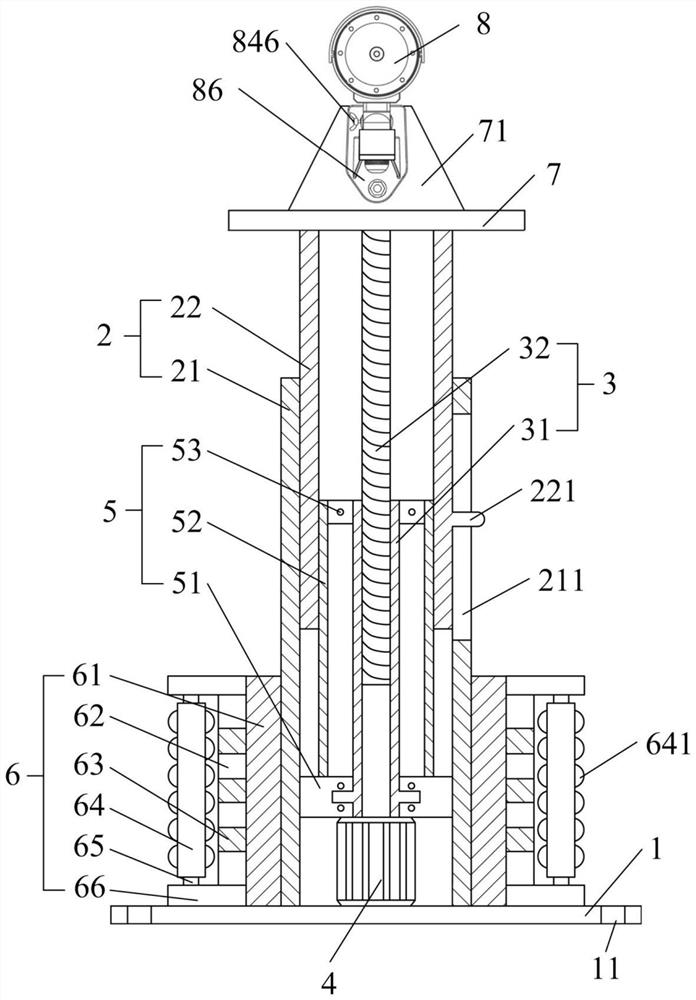
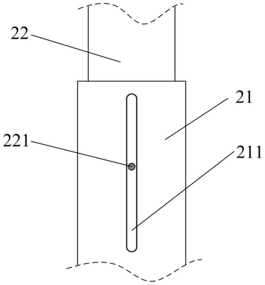
[0035] Embodiment 1: Refer to the device of the present invention figure 1 As shown, a monitoring device for collision prevention includes a base plate 1, the upper end of the base plate 1 is provided with a casing telescopic structure 2; the casing telescopic structure 2 includes an outer sleeve 21 and an inner tube 22, and the outer sleeve 21 is vertically fixed on the On the upper end of the base plate 1, the outer sleeve 21 is sleeved with a telescopic inner tube 22, the top of the inner tube 22 is fixedly provided with a support plate 7, and the support plate 7 is detachably mounted with a camera body 8, the upper end of the base plate 1, the outer sleeve The outer side of 21 is provided with anti-collision structure 6 along the circumferential direction.

[0036] Specifically, as figure 1 As shown, the anti-collision structure 6 includes a pressure-bearing cylinder 61 arranged on the periphery of the outer sleeve 21, and the upper and lower ends of the pressure-bearing ...


PUM


Abstract

The invention belongs to the technical field of security and protection monitoring, and particularly relates to anti-collision monitoring equipment which comprises a bottom plate, and a sleeve telescopic structure is arranged at the upper end of the bottom plate; the sleeve telescopic structure comprises an outer sleeve and an inner pipe, the outer sleeve is vertically fixed at the upper end of the bottom plate, the telescopic inner pipe is sleeved with the outer sleeve, a supporting plate is fixedly arranged at the top end of the inner pipe, and a camera body is installed on the supporting plate; an anti-collision structure is arranged on the bottom plate and comprises a pressure-bearing barrel arranged on the periphery of the outer sleeve, annular check rings are arranged at the upper end and the lower end of the pressure-bearing barrel, an elastic barrel is arranged between the two annular check rings and located on the outer side of the pressure-bearing barrel, a plurality of damping springs are evenly arranged in the elastic barrel, and a plurality of rotating shafts are arranged between the two annular check rings and located on the outer side of the elastic barrel; and a roller is arranged on each rotating shaft, and a plurality of elastic protrusions are evenly arranged on the outer surface of each roller. According to the anti-collision monitoring equipment, by arranging a height adjusting structure and the anti-collision structure, safety monitoring can be achieved while the monitoring range is adjusted according to needs.

Description

technical field [0001] The invention belongs to the technical field of security monitoring, and in particular relates to a monitoring device for collision avoidance. Background technique [0002] The monitoring system is one of the most widely used systems in the security system. The monitoring system is generally composed of front-end monitoring equipment and back-end software. The monitoring system uses the camera in the monitoring equipment to collect image information and then transmits it to the back-end through the line. It can Real-time, visual and true reflection of the monitored object not only greatly prolongs the observation distance of the human eye, but also expands the function of the human eye. It can replace manual monitoring for a long time in harsh environments, allowing people to see Monitor and record everything that actually happens on site. [0003] At present, monitoring equipment is used in highways, urban roads, and construction sites, but the exist...

Claims


Application Information

Patent Timeline
Patent Type & Authority Applications(China)
IPC IPC(8): F16M11/04F16M11/10F16M11/18F16M11/28F16F15/08H04N5/225
CPCF16M11/04F16M11/10F16M11/18F16M11/28F16F15/08H04N23/50
Inventor 叶晴
Owner 西安发威电子科技有限公司
Why Eureka
Try Eureka