


Quick Research
Generate reliable direction feasibility study reports for your R&D in just a few steps.

Technical Q&A
Discover and master advanced knowledge NOW. Basics, ideas, possibilities, all at once.

Find Solutions
As an expert in R&D theories, this can generate solutions to your technical problems instantly.

Evaluate Feasibility
Analyze your overall solution with one click, know your potential R&D risks in advance.

Monitor Landscape
Get weekly tech updates, stay abreast of the latest tech innovations and key insights.
Coal mine tunneling device
A technology for coal mines and installation columns, which is applied to mining equipment, mine roof supports, earthwork drilling and mining, etc., and can solve the problems of long time for breaking rocks and low work efficiency
- Summary
- Abstract
- Description
- Claims
- Application Information
AI Technical Summary
Problems solved by technology
Method used
Image


Examples
Embodiment 1
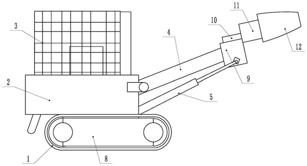
[0031] The embodiment is basically as attached figure 1 Shown: a kind of coal mine tunneling device, comprises load-bearing base 8, walking belt 1 installed on load-bearing base 8, drill bit 12 and the power part that drives drill bit 12 to rotate, and walking belt 1 is crawler belt in the prior art, does not describe here To repeat, the load-bearing base 8 is connected with a fixed box 2, the fixed box 2 is hinged with a control lever 4, and the end of the control lever 4 away from the fixed box 2 is fixedly connected with a drive box 9 by bolts, and the drive box 9 is provided with a drive box for driving the drill bit. 12 reciprocating drive parts, the fixed box 2 is hinged with the control cylinder 5, and the output shaft of the control cylinder 5 is hinged with the drive box 9.
[0032] Such as figure 2 As shown, in this embodiment, the driver includes a mounting column 14 and a rotating plate 13, the mounting column 14 is welded and fixed to the fixed box 2, and the mo...
Embodiment 2
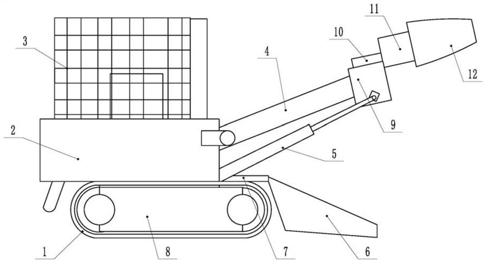
[0042] Such as image 3 As shown, a coal mine excavation device differs from Embodiment 1 in that: the fixed box 2 is provided with a conveyor belt 7 for transporting crushed stones, the fixed box 2 is fixed with a shovel 6 by bolts, and the left end of the shovel 6 is connected to the Conveyor belt 7 links to each other, and shovel plate 6 is positioned at the same side of fixed case 2 with drill bit 12, and conveyer belt 7 adopts the conveyer belt in the prior art, and shovel plate 6 has the inclined-plane that inclines downward.
[0043] to combine Figure 4 As shown, two spatulas are rotationally connected on the slope of the spatula 6. In this embodiment, the spatulas all include a rotating rod 25 and a plurality of blades 24. A shoveling motor (not shown) that drives the rotating rod 25 to rotate is provided inside, and a plurality of blades 24 are evenly distributed along the circumferential direction of the rotating rod 25 .
[0044] In practical application, when th...
Embodiment 3
[0046] Such as Figure 5 Shown, a kind of coal mine excavation device, and the difference of embodiment one is: in the present embodiment, the top of fixed box 2 is connected with temporary supporting device, and in the present embodiment, temporary supporting device comprises base plate 26 and driving unit, and base plate 26 is vertically welded and fixed with a guide plate 28, the guide plate 28 is a rectangular plate-shaped structure, and the vertical slide on the guide plate 28 is connected with an installation box 29. In the present embodiment, the guide plate 28 is vertically provided with a strip groove, and the installation box 29 rear side ( figure 1 Angle of view) a slider 17 (not shown) is welded and fixed, and the slider 17 is inserted into the bar-shaped groove and vertically slides and fits with the bar-shaped groove.
[0047] The drive unit is used to drive the installation box 29 to reciprocate and slide vertically. In this embodiment, there are two drive unit...
PUM
 Abstract
Description
Claims
Application Information
 - R&D Engineer
- R&D Manager
- IP Professional
- Industry Leading Data Capabilities
- Powerful AI technology
- Patent DNA Extraction
Browse by: Latest US Patents, China's latest patents, Technical Efficacy Thesaurus, Application Domain, Technology Topic, Popular Technical Reports.
© 2024 PatSnap. All rights reserved.Legal|Privacy policy|Modern Slavery Act Transparency Statement|Sitemap|About US| Contact US: help@patsnap.com