
Mounting position driving device of annular mounting head

A technology of driving device and placement head, which is applied in the direction of assembling printed circuits, electrical components, and electrical components with electrical components, which can solve the problems of inflexible placement process and low utilization rate of placement heads, so as to improve flexibility and Accuracy, the effect of improving placement quality and placement efficiency

Pending Publication Date: 2021-05-07
SHENZHEN FAROAD INTELLIGENT EQUIP CO LTD
View PDF0 Cites 0 Cited by
  • Summary
  • Abstract
  • Description
  • Claims
  • Application Information

AI Technical Summary

Problems solved by technology

There are also some ring-shaped mounting heads in the prior art, but the existing ring-shaped mounting heads can only perform vertical mounting processes for specific equipment, the mounting process is not flexible enough, and the utilization rate of the mounting heads is low

Method used


Image

  • Mounting position driving device of annular mounting head
  • Mounting position driving device of annular mounting head
  • Mounting position driving device of annular mounting head

Examples


Embodiment Construction

[0022] The idea, specific structure and technical effects of the present invention will be clearly and completely described below in conjunction with the embodiments and accompanying drawings, so as to fully understand the purpose, features and effects of the present invention. Apparently, the described embodiments are only some of the embodiments of the present invention, rather than all of them. Based on the embodiments of the present invention, other embodiments obtained by those skilled in the art without creative efforts belong to The protection scope of the present invention. In addition, all the connection / connection relationships involved in the patent do not simply refer to the direct connection of components, but mean that a better connection structure can be formed by adding or reducing connection accessories according to specific implementation conditions. The various technical features in the invention can be combined interactively on the premise of not conflictin...


PUM


Abstract

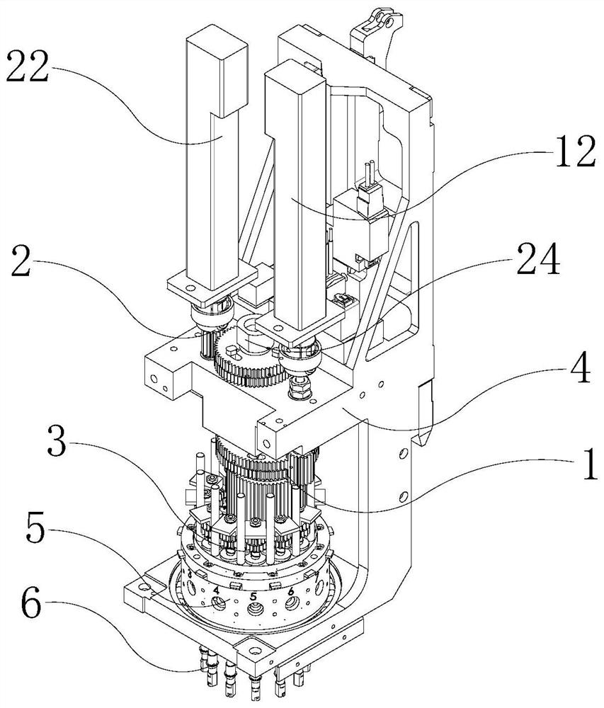
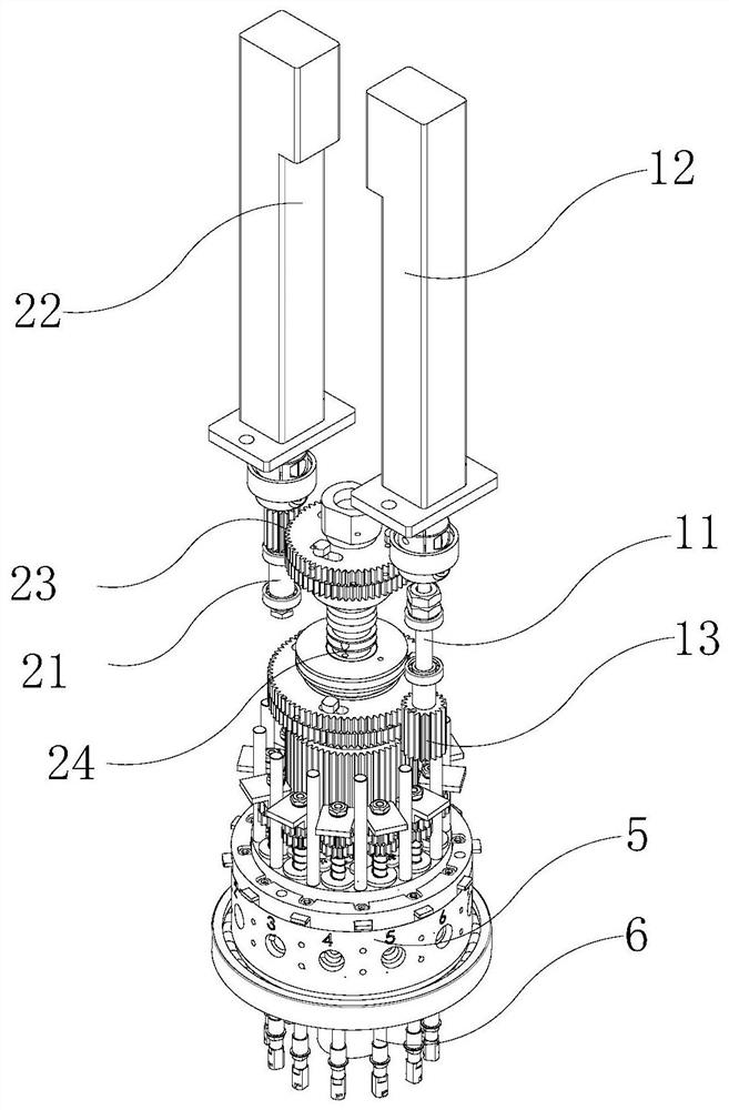
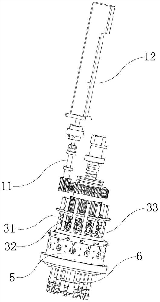
The invention discloses a mounting position driving device of an annular mounting head. The device comprises a mounting frame, a mounting seat and a plurality of mounting rods, the mounting seat is arranged on the mounting frame, the plurality of mounting rods are annularly arranged on the mounting seat, the mounting frame and the mounting seat are also provided with a mounting rod driving device, and the mounting rod driving device is used for driving the mounting seat and the mounting rods arranged around the mounting seat to integrally rotate and driving each mounting rod to rotate. The mounting rods arranged on the mounting seat are driven while the mounting frame and the mounting seat are fixed, so that the mounting rods not only can perform mounting during mounting, but also can be adjusted after sucking a mounted element. The angle, the position and the like of the mounted element sucked by the mounting rods can correspond to the mounting position on a mounting plate, so that the mounting flexibility and accuracy are improved, and the mounting quality and the mounting efficiency are improved.

Description

technical field [0001] The invention relates to a placement head drive, in particular to a placement position drive device for a circular placement head. Background technique [0002] Surface mount technology SMT is a comprehensive system involving electronic components, assembly equipment, welding methods and assembly auxiliary materials, which is used to assemble (also known as mounting) electronic components on printed circuit boards (CB). technology. The main equipment of the SMT assembly line is composed of screen printing machine, placement machine, dispensing machine, welding machine and various process testing equipment. The placement machine is the most critical equipment. It quickly and accurately mounts SMD components to the pad positions on the PCB through several actions such as pick-up, displacement, positioning, and placement of the placement head. [0003] The placement head is the core component of the surface mount technology. The placement machine common...

Claims


Application Information

Patent Timeline
IPC IPC(8): H05K3/30H05K13/04
CPCH05K3/30H05K13/04
Inventor 杨帮合贾孝荣陈金亮贾孝良
Owner SHENZHEN FAROAD INTELLIGENT EQUIP CO LTD
Learn More