High-rotating-speed motor and assembling method thereof

A high-speed, casing technology, applied in the direction of electromechanical devices, electric components, manufacturing motor generators, etc., can solve the problems of high operating noise and easy resonance, etc., to reduce electromagnetic noise, reduce resonance and noise, and not easy to resonate Effect

Active Publication Date: 2021-05-07
SHENZHEN FEIYIDA MOTOR LTD CO
View PDF6 Cites 2 Cited by
  • Summary
  • Abstract
  • Description
  • Claims
  • Application Information

AI Technical Summary

Problems solved by technology

[0002] Because of the high speed, the volume of the high-speed motor is much smaller than that of the ordinary dry motor, and the high-speed motor cancels the deceleration mechanism of Chuanrong. The high-speed motor has high power density, effectively saves materials, high transmission efficiency, and fast dynamic response. However, the electrical appliances used by consumers on the market, such as fans, hair dryers, vacuum cleaners and other electrical appliances, are prone to resonance when running at high speed, and the operating noise is loud

Method used


Image

  • High-rotating-speed motor and assembling method thereof
  • High-rotating-speed motor and assembling method thereof
  • High-rotating-speed motor and assembling method thereof

Examples


Embodiment Construction

[0030] The technical solutions of the present invention will be clearly and completely described below in conjunction with the accompanying drawings. Apparently, the described embodiments are some of the embodiments of the present invention, but not all of them.

[0031] The components of the embodiments of the invention generally described and shown in the figures herein may be arranged and designed in a variety of different configurations. Accordingly, the following detailed description of the embodiments of the invention provided in the accompanying drawings is not intended to limit the scope of the claimed invention, but merely represents selected embodiments of the invention.

[0032] Based on the embodiments of the present invention, all other embodiments obtained by persons of ordinary skill in the art without making creative efforts belong to the protection scope of the present invention.

[0033] In the description of the present invention, it should be noted that the...


PUM


Abstract

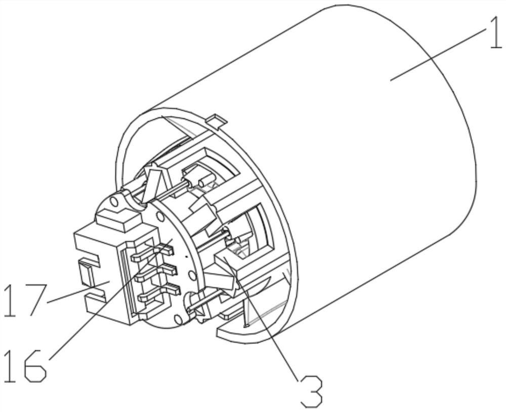
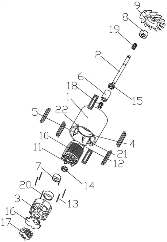
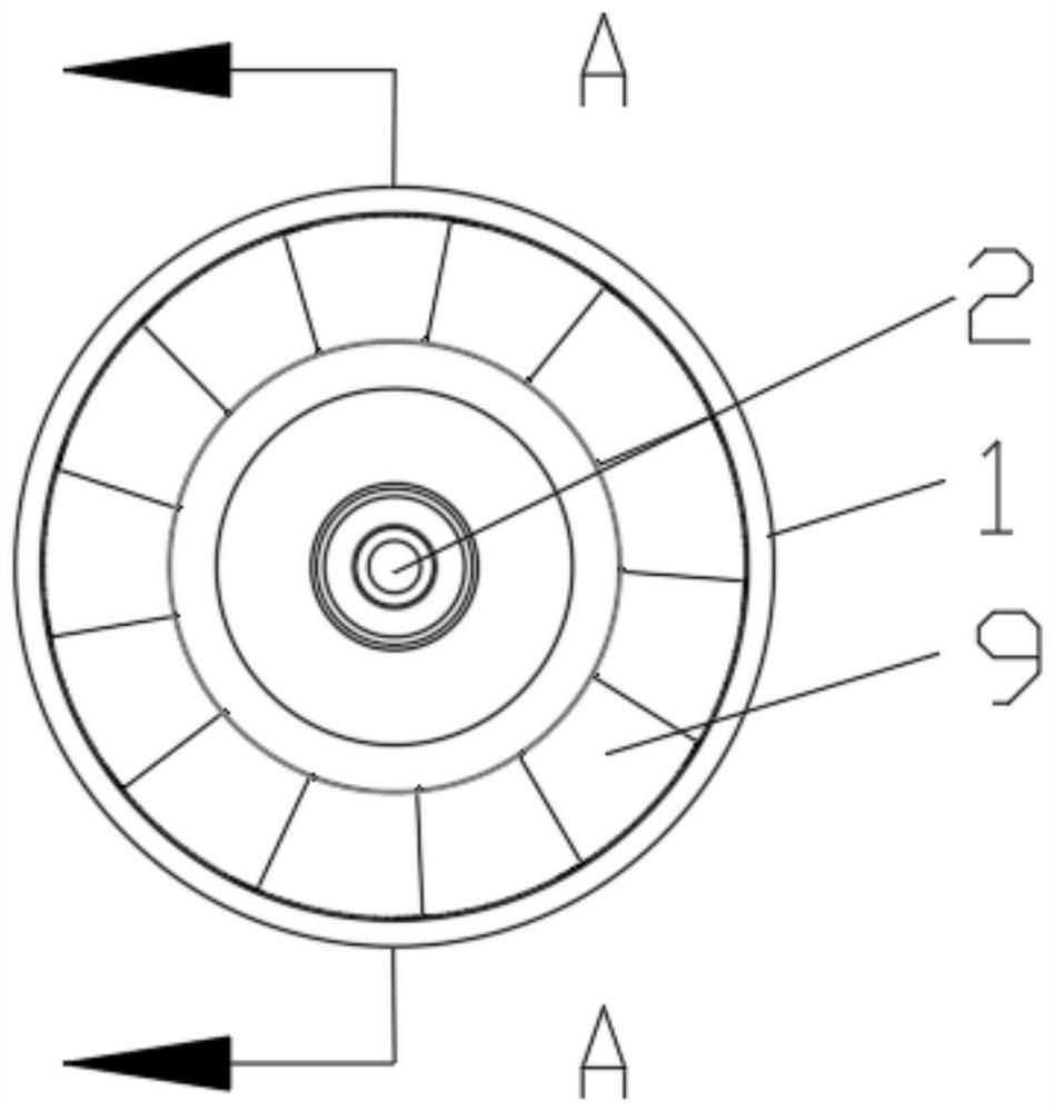
The invention discloses a high-rotating-speed motor and an assembling method thereof. The high-rotating-speed motor comprises a machine shell, a rotating shaft and a bearing sleeve, wherein the machine shell is of an annular structure with the left end and the right end open, an installation ring coaxial with the machine shell is arranged in the machine shell, the outer diameter of the installation ring is smaller than the inner diameter of the machine shell, the length of the installation ring in the left-right direction is smaller than the length of the machine shell in the left-right direction, a plurality of air guide pieces are evenly distributed between the installation ring and the inner wall of the machine shell, a stator installation cavity and a bearing installation cavity are sequentially formed in the installation ring from left to right; an annular protruding part is arranged in the middle of a stator installation cavity of the installation ring, the outer wall of the right portion of the bearing sleeve is matched with the inner wall of the left portion of the machine shell, the outer wall of the right portion of the bearing sleeve is inserted into the inner wall of the left portion of the machine shell, the rotating shaft is inserted into the bearing sleeve and the machine shell in the left-right direction, the middle of the rotating shaft is sleeved with a magnetic ring, and a stator assembly is mounted in the stator mounting cavity. The high-rotating-speed motor has the advantages of being not prone to resonance, low in noise and the like.

Description

technical field [0001] The technical field of motors of the present invention specifically relates to a high-speed motor and an assembly method thereof. Background technique [0002] Because of the high speed, the volume of the high-speed motor is much smaller than that of the ordinary dry motor, and the high-speed motor cancels the deceleration mechanism of Chuanrong. The high-speed motor has high power density, effectively saves materials, high transmission efficiency, and fast dynamic response. However, the electrical appliances used by consumers on the market, such as fans, hair dryers, vacuum cleaners and other electrical appliances, are prone to resonance when running at high speed, and the operating noise is large. Contents of the invention [0003] In order to solve the deficiencies in the prior art, the present invention provides a high-speed motor with low resonance and low noise and an assembly method thereof. [0004] In order to solve the problems of the tech...

Claims


Application Information

Patent Timeline
Patent Type & Authority Applications(China)
IPC IPC(8): H02K5/16H02K7/00H02K5/24H02K9/06H02K15/00
CPCH02K5/161H02K7/003H02K5/24H02K9/06H02K15/00
Inventor 陈少友古勇吴统松
Owner SHENZHEN FEIYIDA MOTOR LTD CO
Why Eureka
Try Eureka