
Projection lens system

A projection lens and lens technology, applied in the optical field, can solve problems such as easy focus running

Active Publication Date: 2021-05-07
DIGIENGIN OPTOELECTRONICS TAIZHOU LTD CO
View PDF22 Cites 2 Cited by
  • Summary
  • Abstract
  • Description
  • Claims
  • Application Information

AI Technical Summary

Problems solved by technology

[0005] The purpose of the present invention is to provide a projection lens system to solve the problem that the existing projection lens is easy to run out of focus when working at high temperature

Method used


Image

  • Projection lens system
  • Projection lens system
  • Projection lens system

Examples


Embodiment Construction

[0045] In order to facilitate the understanding of the present invention, the present invention will be described more fully below with reference to the associated drawings. Several embodiments of the invention are shown in the drawings. However, the present invention can be embodied in many different forms and is not limited to the embodiments described herein. Rather, these embodiments are provided so that the disclosure of the present invention will be thorough and complete.

[0046] It should be noted that when an element is referred to as being “fixed on” another element, it may be directly on the other element or there may be an intervening element. When an element is referred to as being "connected to" another element, it can be directly connected to the other element or intervening elements may also be present. The terms "vertical," "horizontal," "left," "right," and similar expressions are used herein for purposes of illustration only.

[0047] Unless otherwise def...


PUM

PropertyMeasurementUnit
Focal lengthaaaaaaaaaa

Abstract

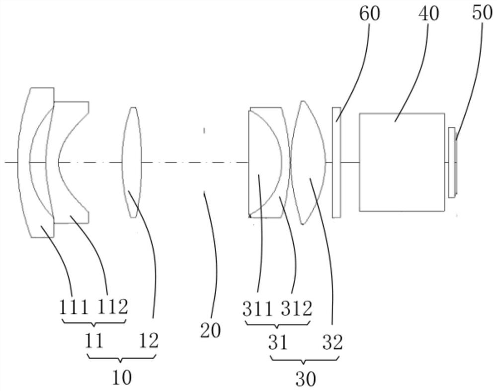
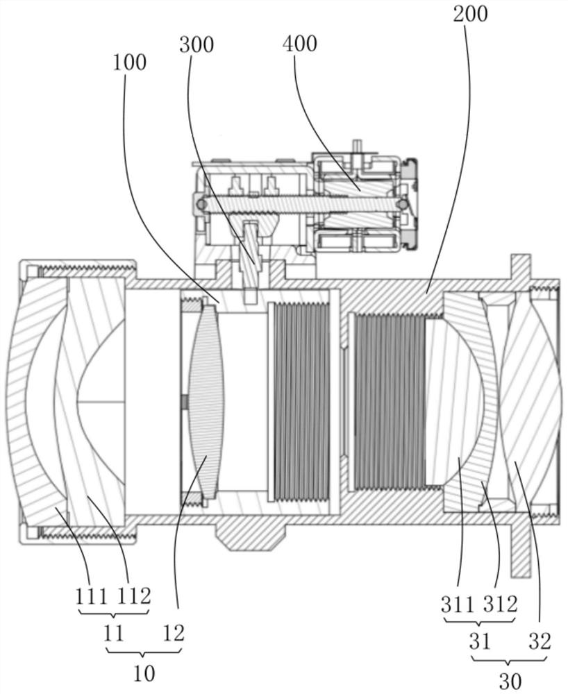
The invention provides a projection lens system. The system comprises, sequentially arranged, a first refraction lens group, wherein the first refraction lens group comprises at least two coaxially arranged spherical lenses; an aperture stop; a second refractive lens group, wherein the second refractive lens group comprises at least one even aspheric lens; and an equivalent prism and a micro display chip. The position of at least one spherical lens in the first refraction lens group can be coaxially adjusted under the condition that the total length of the first refraction lens group is not changed. According to the projection lens system, the position can be coaxially adjusted under the condition that the total length of the first refraction lens group is not changed through one spherical lens in the first refraction lens group, so that defocusing caused by temperature or tolerance compensation during lens assembly can be compensated, and the projection lens system has the advantages of compact lens structure, high definition, small distortion, good tolerance implementation and the like.

Description

technical field [0001] The invention relates to the field of optical technology, in particular to a projection lens system. Background technique [0002] As the role of projection equipment in life becomes more and more diversified, the fields of application are also becoming more and more abundant, and more optical machines need to be embedded in micro-projectors. The requirements for the projection lens are also getting higher and higher, the structure needs to be more compact, the projection range is larger, the imaging effect is better, and the projection lens with good craftsmanship has become the mainstream, and it can also make the micro projection truly enter the home theater. [0003] A galvanometer is added between the lens and the prism, and the projection lens participates in imaging through the set galvanometer, so that the resolution of the projection lens device when it is still is the inherent resolution of the DMD chip, and the galvanometer is a higher resol...

Claims


Application Information

Patent Timeline
IPC IPC(8): G03B21/14G03B21/00G02B13/22G02B13/18G02B13/00G02B1/00
CPCG03B21/142G03B21/147G02B13/18G02B13/006G02B13/22G02B1/00G03B21/008
Inventor 印晓丽李林翟金会
Owner DIGIENGIN OPTOELECTRONICS TAIZHOU LTD CO
Learn More