
Optical fiber ring structure and optical fiber ring simulation temperature measurement structure

An optical fiber ring and optical fiber technology, applied in the field of optical fiber inertial navigation, can solve the problems of one-sided temperature distribution of the optical fiber ring, affecting the effect of temperature compensation, etc., and achieve the effect of optimizing the temperature compensation method and improving the accuracy

Active Publication Date: 2021-05-07
HUNAN AEROSPACE ELECTROMECHANICAL EQUIP & SPECIAL MATERIAL INST
View PDF8 Cites 0 Cited by
  • Summary
  • Abstract
  • Description
  • Claims
  • Application Information

AI Technical Summary

Problems solved by technology

[0004] The problem to be solved by the present invention is to provide an optical fiber ring structure for the problem that the temperature distribution of the optical fiber ring reflected by the measurement results of the existing temperature measurement equipment is very one-sided, which further greatly affects the effect of subsequent temperature compensation

Method used


Image

  • Optical fiber ring structure and optical fiber ring simulation temperature measurement structure
  • Optical fiber ring structure and optical fiber ring simulation temperature measurement structure
  • Optical fiber ring structure and optical fiber ring simulation temperature measurement structure

Examples


Embodiment Construction

[0043] The following will clearly and completely describe the technical solutions in the embodiments of the present application with reference to the accompanying drawings of the present application. Apparently, the described embodiments are only some of the embodiments of the present application, not all of them. Based on the embodiments in this application, all other embodiments obtained by persons of ordinary skill in the art without making creative efforts belong to the scope of protection of this application.

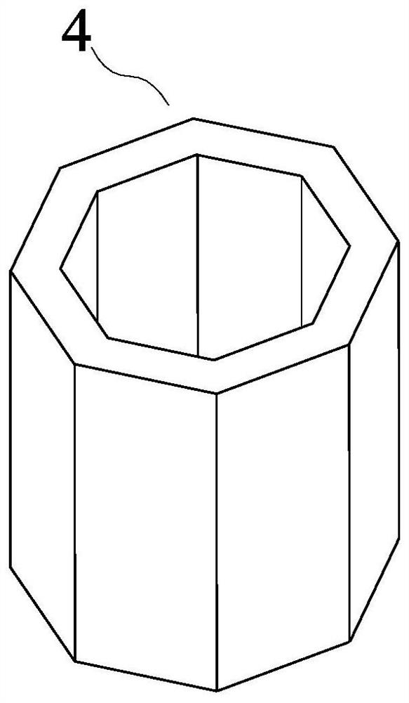
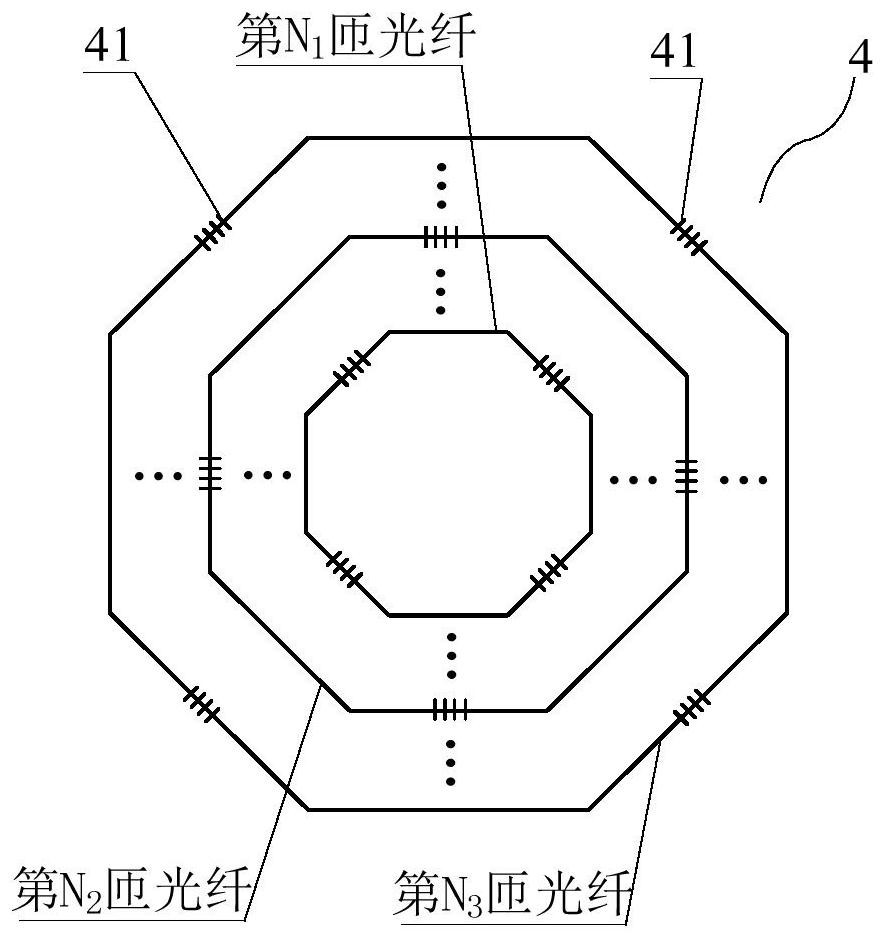
[0044] The present invention provides an optical fiber ring structure, the optical fiber ring structure 4 is a hollow columnar structure and includes M layers of optical fibers arranged in the length direction of the optical fiber ring, M≥2, and the optical fiber ring structure 4 includes L optical fibers, L≥ 1. The i-th optical fiber is wound to form M arranged in the length direction of the optical fiber ring structure 4 i Layers of optical fibers, the number of ...


PUM


Abstract

The invention provides an optical fiber ring structure and an optical fiber ring simulation temperature measurement structure. The optical fiber ring structure is a hollow cylindrical structure and comprises M layers of optical fibers arranged in the length direction of an optical fiber ring, M is greater than or equal to 2, the optical fiber ring structure comprises L optical fibers, L is greater than or equal to 1, the ith optical fiber is wound to form Mi layers of optical fibers arranged in the length direction of the optical fiber ring structure, The number of turns of each layer of optical fiber of the optical fiber ring structure is N, and each turn of optical fiber is encircled into a regular polygon with K sides; and each layer of optical fiber of the optical fiber ring structure is provided with at least three Bragg grating sensors, a graph enclosed by the Bragg grating sensors on each layer of optical fiber of the optical fiber ring structure is a graph symmetrical about the central axis of the optical fiber ring structure, and the Bragg grating sensors are arranged on the edges of a regular polygon.

Description

technical field [0001] The invention belongs to the technical field of optical fiber inertial navigation, and applies a new analog temperature measurement structure of an optical fiber ring based on an optical fiber grating to the analog measurement of the temperature of an optical fiber gyroscope optical fiber ring. Background technique [0002] The fiber optic ring is an important component in the fiber optic gyroscope. It is used to sense the angular rate. When the fiber optic ring rotates axially, a Sagnac phase difference will be generated when the two beams of optical signals propagating in opposite directions in the fiber optic ring arrive at the same point. After the two light waves pass through the fiber optic ring, the phase changes caused by temperature changes are different (that is, the Shupe effect). The Shupe effect seriously affects the accuracy of the fiber optic gyroscope. In high-precision fiber optic gyroscopes, temperature compensation methods are require...

Claims


Application Information

Patent Timeline
Patent Type & Authority Applications(China)
IPC IPC(8): G01C19/72G01K15/00
CPCG01C19/72G01K15/00
Inventor 岑礼君
Owner HUNAN AEROSPACE ELECTROMECHANICAL EQUIP & SPECIAL MATERIAL INST
Learn More