Based on foldable warp knitting machine fixing bracket for easy transportation

A fixed bracket and foldable technology, applied in warp knitting, textiles, papermaking, knitting, etc., can solve the problems of occupying a large space, lack of practicability, and inconvenient height adjustment and movement of the fixed bracket, so as to save space, The effect of convenient subsequent transportation and strong practicability

Active Publication Date: 2022-05-10
CHANGDE TEXTILE MACHINERY
View PDF0 Cites 0 Cited by
  • Summary
  • Abstract
  • Description
  • Claims
  • Application Information

AI Technical Summary

Problems solved by technology

[0002] Use one or several groups of yarns arranged in parallel to form a knitted fabric at the same time on all the working needles of the warp feeding machine. This method is called warp knitting, and the fabric is called warp knitted fabric. The warp knitting machine is called a warp knitting machine. When the warp knitting machine is in use, it needs to use a fixed bracket to support the coil, so that the yarn can be fed into the working needle of the machine for fine knitting. However, the current fixed bracket is inconvenient to adjust the height and Mobile, and when not in use, the fixed bracket cannot be folded. The larger fixed bracket is located in the warehouse, which takes up a lot of space and lacks practicability. In view of this, we propose a warp knitting machine fixed bracket

Method used


Image

  • Based on foldable warp knitting machine fixing bracket for easy transportation
  • Based on foldable warp knitting machine fixing bracket for easy transportation
  • Based on foldable warp knitting machine fixing bracket for easy transportation

Examples


Embodiment 1

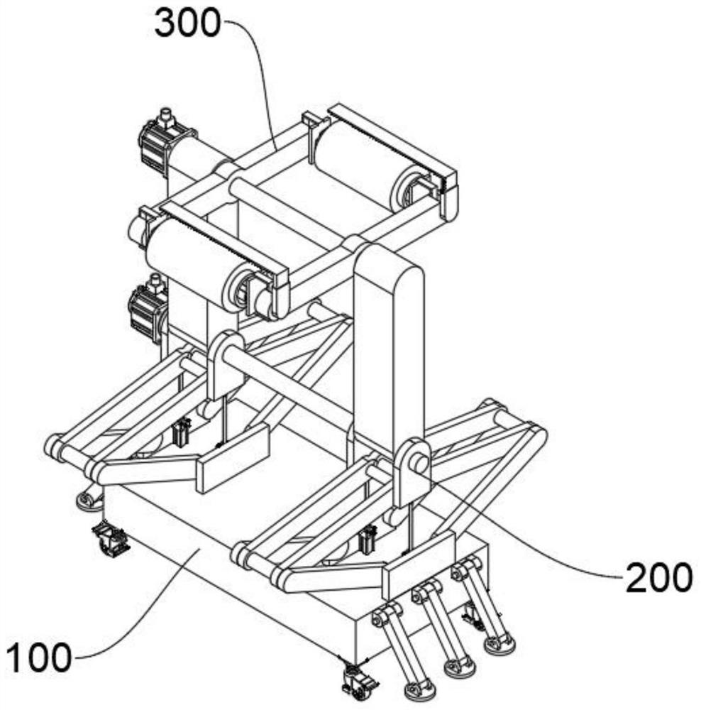
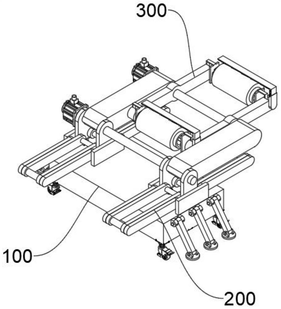
[0048] see Figure 1-Figure 15 As shown, the present embodiment provides a warp knitting machine fixing bracket based on a foldable type for easy transportation, which at least includes:

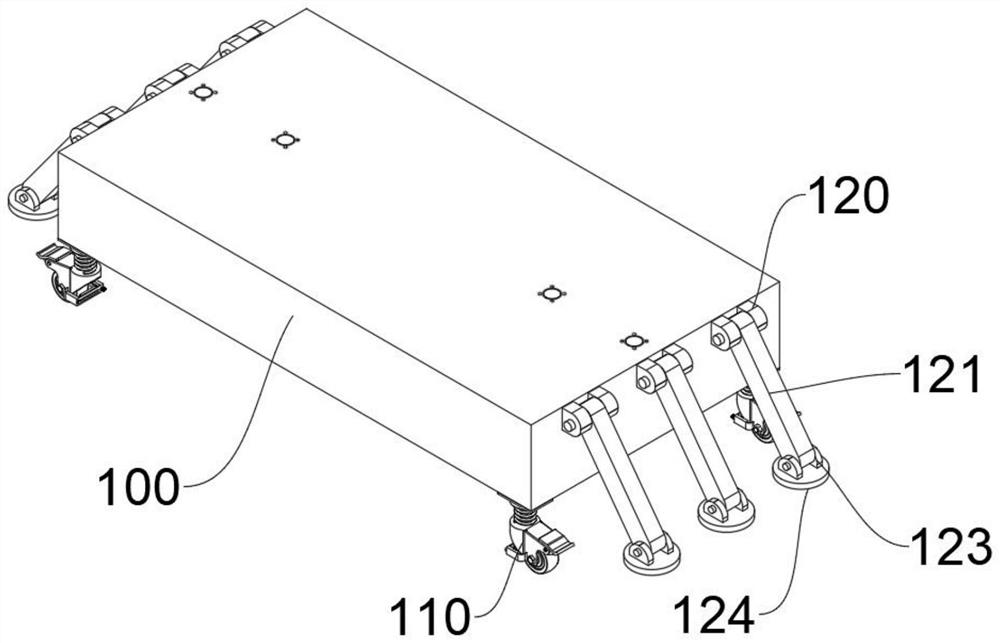
[0049] The bottom plate 100 and the bottom of the bottom plate 100 are provided with universal wheels 110 near the corners. The top of the universal wheels 110 is provided with a buffer spring 111, and the top of the buffer spring 111 is fixedly connected with a mounting plate 112. By setting the buffer spring 111, the When the vibration is bumpy, the buffer spring 111 is compressed, and under the action of the elastic force of the buffer spring 111, the damage to the base plate 100 caused by the rigid impact of the vibration can be buffered, which is beneficial to prolong the service life. The top of the mounting plate 112 is fixed on the bottom of the base plate 100 by bolt threads. By pushing and pulling the bottom plate 100, the universal wheel 110 is rotated, so that the universal wheel...


PUM


Abstract

The invention relates to the technical field of warp knitting machine fixing, in particular to a foldable warp knitting machine fixing bracket for easy transportation. It at least includes: a bottom plate, a lifting mechanism and a clamping and fixing bracket. The lifting mechanism includes two symmetrical fixing frames, and the two fixing frames are respectively fixed on the top of the bottom plate near the edge. The first articulated rod, the end of the first articulated rod rotates on the inner wall of the fixed frame through the rotating shaft, and two symmetrical second articulated rods are rotated between the two first articulated rods, and the ends of the four second articulated rods are hinged A rotating fork is provided, the end of the second hinged rod is arranged on the inner wall of the rotating fork through the rotating shaft, the end of the push rod of the electric push rod is fixedly connected to the bottom of the rotating fork near the edge, and the outer wall of the electric push rod is embedded in the top of the bottom plate, the present invention can The coils needed by the warp knitting machine are fixed, which is convenient for transportation, and can be folded to save space when not in use.

Description

technical field [0001] The invention relates to the technical field of warp knitting machine fixing, in particular to a foldable warp knitting machine fixing bracket for easy transportation. Background technique [0002] Use one or several groups of yarns arranged in parallel to form a knitted fabric at the same time on all the working needles of the warp feeding machine. This method is called warp knitting, and the fabric is called warp knitted fabric. The warp knitting machine is called a warp knitting machine. When the warp knitting machine is in use, it needs to use a fixed bracket to support the coil, so that the yarn can be fed into the working needle of the machine for fine knitting. However, the current fixed bracket is inconvenient to adjust the height and Mobile, and when not in use, the fixed bracket cannot be folded. The larger fixed bracket is located in the warehouse, which takes up a lot of space and lacks practicability. In view of this, we propose a warp kni...

Claims


Application Information

Patent Timeline
Patent Type & Authority Patents(China)
IPC IPC(8): D04B27/00
CPCD04B27/00
Inventor 陈鹏陈海军严中华
Owner CHANGDE TEXTILE MACHINERY
Why Eureka
Try Eureka