Gas-switching ironmaking device

A technology of gas and furnace body, which is applied in the direction of fluidized bed furnace, etc., can solve the problems of wasting and exhausting heat, trouble, labor, etc., and achieve the effect of full utilization and sufficient heat

Pending Publication Date: 2021-05-07
卢长丽
View PDF1 Cites 1 Cited by
  • Summary
  • Abstract
  • Description
  • Claims
  • Application Information

AI Technical Summary

Problems solved by technology

[0005] In order to overcome the disadvantages of wasting and discharging heat in the prior art, the discharge of molten iron and impurities cannot be controlled, and the closed door is easy to dirty the furnace body, which is laborious and troublesome. An ironmaking plant that uses exhaust heat to autonomously control and maintain closed doors and open baffles for gas conversion

Method used


Image

  • Gas-switching ironmaking device
  • Gas-switching ironmaking device
  • Gas-switching ironmaking device

Examples


Embodiment 1

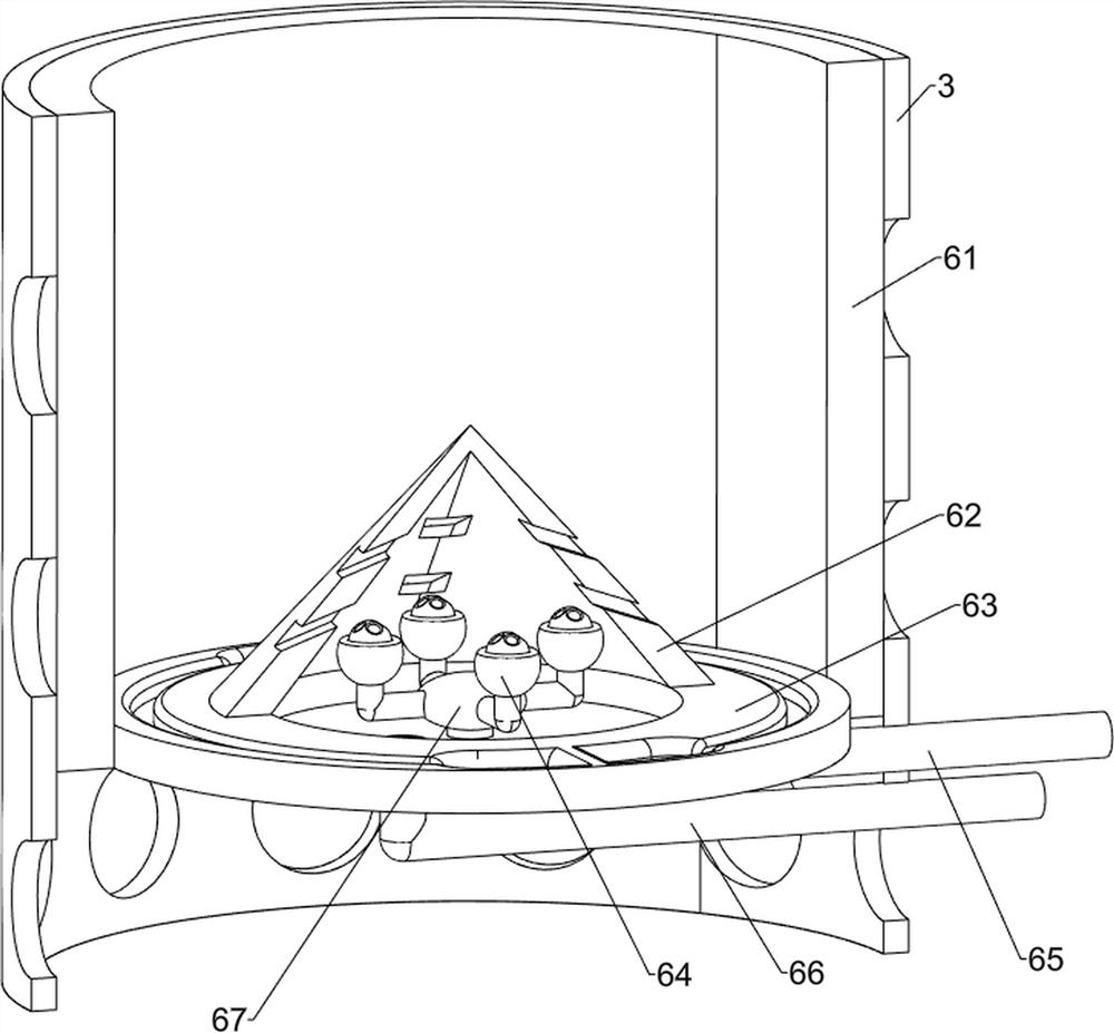
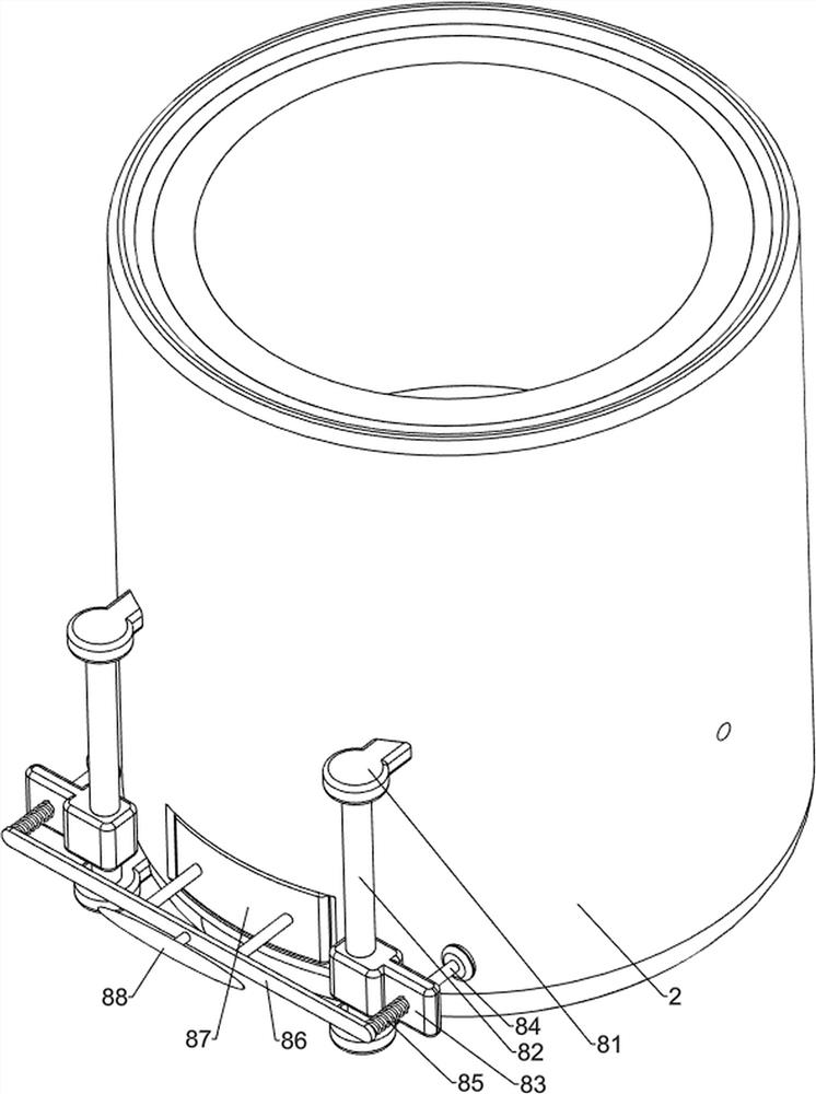
[0030] An ironmaking plant that converts gases, such as figure 1 , figure 2 , image 3 and Figure 4 As shown, it includes a base 1, a feed box 11, a furnace body 2, a heat shield 3, a filter plate 4, a feeding mechanism 5 and a combustion mechanism 6, the upper left side of the base 1 is connected with a feed box 11, and the base 1 The furnace body 2 is connected in the middle on the right side of the upper part, and the inside of the furnace body 2 is connected with a heat insulation board 3, and the inner lower side of the furnace body 2 is connected with a filter plate 4, and the filter plate 4 is located at the lower side of the heat insulation board 3, and the feed box 11 is equipped with a There is a feeding mechanism 5, and a combustion mechanism 6 is arranged inside the heat shield 3.

[0031] The feeding mechanism 5 includes a material pipe 51, a discharge port 52, a first motor 53, a rotating shaft 54, and a coil 55. The feed box 11 is connected with a material ...

Embodiment 2

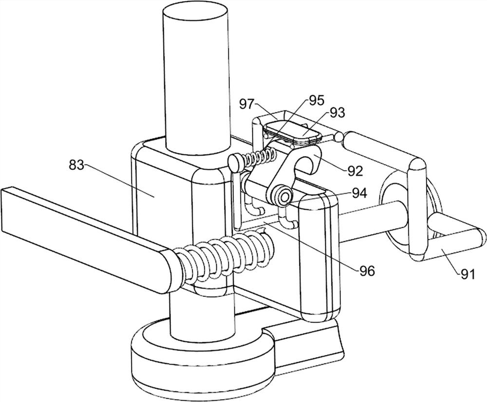
[0035] On the basis of Example 1, such as figure 1 , figure 2 , Figure 5 , Figure 6 , Figure 7 and Figure 8 As shown, a preheating assembly 7 is also included, and the preheating assembly 7 includes a second motor 71, a fan blade 72, a support frame 73, an air box 74, a suction hood 75 and a delivery pipe 76, and the upper part of the rear side of the furnace body 2 is connected in the middle There is a support frame 73, the upper part of the rear side of the support frame 73 is connected with a bellows 74, the right side of the upper part of the bellows 74 is equipped with a second motor 71, the left side of the output shaft of the second motor 71 is connected with a fan blade 72, the output shaft of the second motor 71 is connected with the bellows 74 rotary connection, the fan blade 72 is located inside the bellows 74, the front side of the bellows 74 is connected with a suction cover 75 in the middle, the suction cover 75 is located on the upper side of the furnac...


PUM


Abstract

The invention relates to an ironmaking device, in particular to a gas-switching ironmaking device. The technical problem of the invention is to provide the gas-switching ironmaking device which can automatically switch gas to complete ironmaking, fully utilize discharged heat and autonomously control and maintain the opening of a closing door and a material blocking plate. The gas-switching ironmaking device comprises a base, a furnace body, a thermal insulation plate, a filter plate, a feeding mechanism and a combustion mechanism, and a feeding box is connected to the middle of one side of the upper portion of the base. The middle of one side of the upper part of the base is connected with the furnace body. The thermal insulation plate is connected in the furnace body. The filter plate is connected to the lower side in the furnace body and located on the lower side of the thermal insulation plate. The feeding mechanism is arranged in the feeding box. The combustion mechanism is arranged in the thermal insulation plate. A second motor is started to drive fan blades to rotate, hot gas in the furnace body is sucked in through a gas suction cover and conveyed to the raw material position of the feeding box through a conveying pipe, the effect of preheating raw materials is achieved, heat is more sufficiently utilized, and environment protection and energy conservation are achieved.

Description

technical field [0001] The invention relates to an ironmaking device, in particular to an ironmaking device for converting gas. Background technique [0002] my country's ironmaking began in the Spring and Autumn Period. It is a refining process with a long history. In a nutshell, it is the production process of reducing iron ore with a reducing agent to obtain pig iron at high temperature, and using natural gas to melt raw materials at high temperature. Ironmaking method , is also one of the means of ironmaking. [0003] The existing ironmaking technology of converting gas is to transfer the raw materials to the furnace body, inject natural gas and air, and under the action of the furnace head, melt the raw materials, discharge the molten iron and impurities, and firstly melt the raw materials at high temperature in the furnace body. The heat is completely wasted, the impurity discharge opening is always open, and the impurities keep falling out, which is uncontrollable. If...

Claims


Application Information

Patent Timeline
Patent Type & Authority Applications(China)
IPC IPC(8): C21B11/00C21B13/00C21B15/00
CPCC21B11/00C21B13/00C21B15/00
Inventor 卢长丽
Owner 卢长丽
Why Eureka
Try Eureka