Automatic pulling-out device for wheel axle of mechanical equipment for coal mine

A technology for mechanical equipment and axles, which is applied in the field of automatic pull-off devices for mechanical equipment and axles in coal mines, can solve the problems of mechanical equipment axles stuck, difficult to pull out, unable to pull out, etc.

Pending Publication Date: 2021-05-07
谷成林
View PDF0 Cites 0 Cited by
  • Summary
  • Abstract
  • Description
  • Claims
  • Application Information

AI Technical Summary

Problems solved by technology

[0002] The pulling device is used to pull out the connecting parts of key shafts, counter wheels, gears and other equipment. The shafts of mechanical equipment used in coal mines are likely to cause problems that are difficult to pull out due to long-term use in the harsh environment of coal mines.
[0003] The existing methods for pulling out the axles of mechanical equipment used in coal mines generally use crowbars, steel brazes, steel wire ropes, iron plates, etc. to pull out manually. Due to the constraints of the underground working environment of coal mines, if the axles of mechanical equipment are seriously stuck, they often cannot be pulled out. Therefore, in view of the above problems, an automatic pull-off device for coal mine mechanical equipment axles is proposed

Method used


Image

  • Automatic pulling-out device for wheel axle of mechanical equipment for coal mine
  • Automatic pulling-out device for wheel axle of mechanical equipment for coal mine
  • Automatic pulling-out device for wheel axle of mechanical equipment for coal mine

Examples


Embodiment Construction

[0015] The following will clearly and completely describe the technical solutions in the embodiments of the present invention with reference to the accompanying drawings in the embodiments of the present invention. Obviously, the described embodiments are only some, not all, embodiments of the present invention. Based on the embodiments of the present invention, all other embodiments obtained by persons of ordinary skill in the art without making creative efforts belong to the protection scope of the present invention.

[0016] see Figure 1-4 , the present invention provides a technical solution:

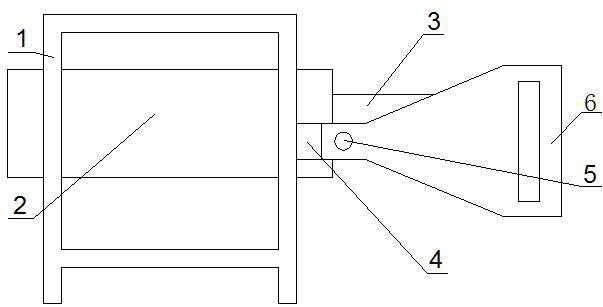
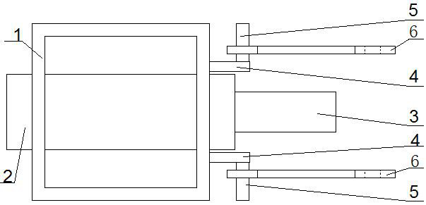
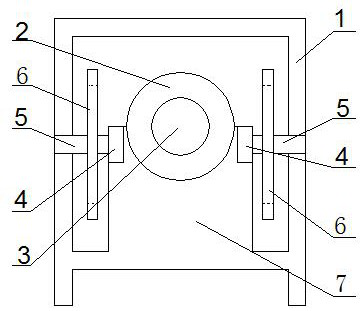
[0017] An automatic pulling-off device for mechanical equipment wheel axles in coal mines, comprising a frame 1, a cylinder body 2, a piston rod 3, a connecting plate 4, a connecting rod 5, a puller plate 6, a front support plate 7 and a rear support plate 8, the The frame 1 is fixed with a front support plate 7 and a rear support plate 8, the cylinder body 2 is fixed on the front...


PUM


Abstract

The invention relates to the technical field of pulling-out devices, in particular to an automatic pulling-out device for a wheel axle of mechanical equipment for a coal mine. The automatic pulling-out device for the wheel axle of the mechanical equipment for the coal mine comprises a frame, a cylinder body, a piston rod, connecting plates, connecting rods, wheel pulling plates, a front supporting plate and a rear supporting plate, wherein the front supporting plate and the rear supporting plate are fixed to the frame; the piston rod can stretch out and draw back in the cylinder body in a reciprocating mode through a medium; the connecting plates are respectively fixed to the left side and the right side of the front supporting plate; the connecting rods are fixed onto the connecting plates; the connecting rods are sleeved with the wheel pulling plates; the wheel pulling plates can rotate and move left and right; and square groove holes are formed in the wheel pulling plates. According to the automatic pulling-out device for the wheel axle of the mechanical equipment for the coal mine provided by the invention, through arranging the connecting plates, the connecting rods and the wheel pulling plates, the space and the angle between the two wheel pulling plates can be adjusted; a wheel edge needing to be pulled out of the axle can be sleeved with the square groove holes formed in the wheel pulling plates; and the axle can be pushed away backwards through the arranged piston rod, and then a wheel is pulled out of the axle, so that the purpose of automatically pulling out the equipment wheel axle is achieved.

Description

technical field [0001] The invention relates to the technical field of pull-off devices, in particular to an automatic pull-off device for mechanical equipment wheel shafts used in coal mines. Background technique [0002] The pulling device is used to pull out the connecting parts of key shafts, counter wheels, gears and other equipment. The shafts of mechanical equipment used in coal mines are likely to be difficult to pull out due to their long-term use in the harsh environment of coal mines. [0003] The existing methods for pulling out the axles of mechanical equipment used in coal mines generally use crowbars, steel brazes, steel wire ropes, iron plates, etc. to pull out manually. Due to the constraints of the underground working environment of coal mines, if the axles of mechanical equipment are seriously stuck, they often cannot be pulled out. Therefore, in view of the above problems, an automatic pull-off device for coal mine mechanical equipment axles is proposed. ...

Claims


Application Information

Patent Timeline
Patent Type & Authority Applications(China)
IPC IPC(8): B23P19/027
CPCB23P19/027
Inventor 谷成林
Owner 谷成林
Why Eureka
Try Eureka