
Flaw detection mechanism and flaw detection scanning device

A technology of scanning device and positioning mechanism, which is applied in manipulators, mechanical bearing testing, manufacturing tools, etc., can solve the problems of workpiece flaw detection, narrow application range of flaw detection devices, and reduced performance of flaw detection devices

Pending Publication Date: 2021-05-04
SHENHUA RAIL & FREIGHT WAGONS TRANSPORT
View PDF7 Cites 2 Cited by
  • Summary
  • Abstract
  • Description
  • Claims
  • Application Information

AI Technical Summary

Problems solved by technology

However, for the detection of workpieces with slopes or arcs, there is nothing to do, and flaw detection cannot be performed on workpieces with slopes or arcs, which leads to a narrow range of application of the flaw detection device and reduces the performance of the flaw detection device.

Method used


Image

  • Flaw detection mechanism and flaw detection scanning device
  • Flaw detection mechanism and flaw detection scanning device
  • Flaw detection mechanism and flaw detection scanning device

Examples


Embodiment Construction

[0032]In order to make the above objects, features and advantages of the present invention more comprehensible, specific implementations of the present invention will be described in detail below in conjunction with the accompanying drawings. In the following description, numerous specific details are set forth in order to provide a thorough understanding of the present invention. However, the present invention can be implemented in many other ways different from those described here, and those skilled in the art can make similar improvements without departing from the connotation of the present invention, so the present invention is not limited by the specific embodiments disclosed below.

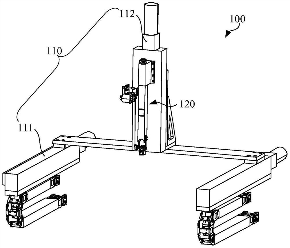
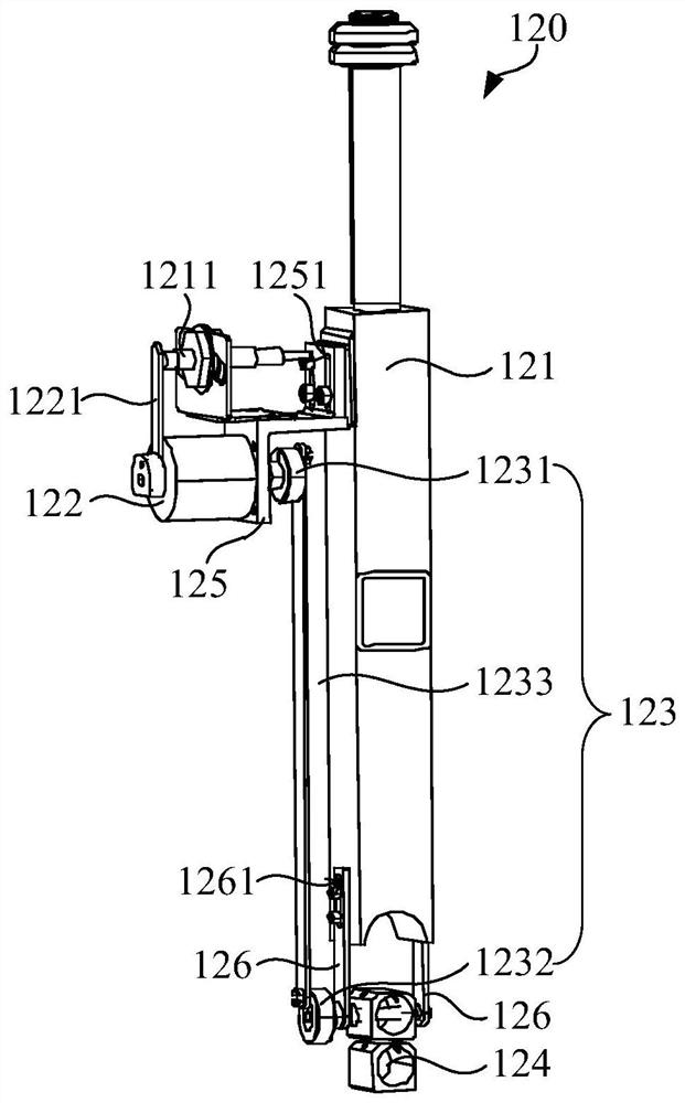
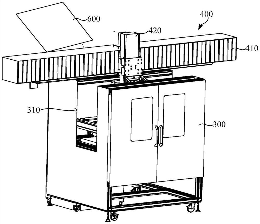
[0033] In one example, please refer to figure 1 , figure 2 and image 3 , a flaw detection mechanism 100 , the flaw detection mechanism 100 includes a flaw detection structure 120 and a first moving structure 110 . The flaw detection structure 120 includes a first mounting base 121 , a...


PUM


Abstract

The invention relates to a flaw detection mechanism and a flaw detection scanning device, a flaw detection structure is driven to move through a first moving structure, so that the flaw detection structure gets close to a workpiece, and the flaw detection structure can perform flaw detection on the workpiece. When the workpiece has a slope surface or an arc-shaped surface, a first driver is started, and a probe is transmitted through a swinging assembly, so that the probe swings on a first mounting seat, the mounting angle of the probe is changed, and one end of the probe can be aligned to the normal direction of the slope surface or the arc-shaped surface of the workpiece; therefore, the probe can perform effective flaw detection on the workpiece, the detection application range is effectively widened, and the use performance of the device is improved. Meanwhile, the first driver and the probe of the flaw detection mechanism are separated, and the first driver and the probe are in transmission through the swing assembly, so that the situation that the first driver enters water and directly drives the probe to cause driving vibration or driving electric field to interfere flaw detection is effectively avoided, and the influence on the reliability of a flaw detection result is avoided.

Description

technical field [0001] The invention relates to the technical field of non-destructive testing, in particular to a flaw detection mechanism and a flaw detection scanning device. Background technique [0002] Non-destructive testing refers to the use of heat, sound, light, electricity, magnetic and other reactions caused by the abnormal internal structure of the material or the existence of defects without damaging or affecting the performance of the tested object, and without destroying the internal organization of the tested object. Change, by means of physical or chemical methods, with the help of modern technology and equipment, the structure, nature, state and type, nature, quantity, shape, position, size, distribution and changes of the internal and surface of the test piece Methods of inspection and testing. [0003] Non-destructive testing is particularly important for the safe operation of mechanical parts. Taking the bearings used in railway vehicles as an example,...

Claims


Application Information

Patent Timeline
IPC IPC(8): G01M13/04B25J18/00
CPCG01M13/04B25J18/00
Inventor 丁颖边志宏王蒙赵普民王洪昆王文刚王萌焦杨马瑞峰陈亮吕松
Owner SHENHUA RAIL & FREIGHT WAGONS TRANSPORT
Learn More