Non-woven fabric winding barrel for mask production

A non-woven fabric and cloth wrapping technology, which is applied in the field of non-woven fabric wrapping tubes for mask production, can solve the problems of lack of humidification structure, high cost, and small humidification range, and achieve good static elimination effect, thorough static elimination, and improved The effect of the humidification effect

Active Publication Date: 2021-05-04
江西艾酷玩具有限公司
View PDF9 Cites 0 Cited by
  • Summary
  • Abstract
  • Description
  • Claims
  • Application Information

AI Technical Summary

Problems solved by technology

[0003]However, due to the thin texture of non-woven fabrics, most of which are thin sheets of a few tenths of a millimeter, friction will occur during transmission. As we all know, friction will generate static electricity. Non-woven fabrics Static electricity will also be generated by friction when feeding materials from the winding drum to the equipment. Masks made of non-woven fabrics with electrostatic effects tend to adhere to dust. This is not allowed for masks with high hygiene requirements. Now The electrostatic treatment method is to humidify the entire workshop to form a humidified environment. However, this method has a large layout range and high cost. Closer to the humidification structure of the cloth, static electricity will still be generated due to friction when the cloth is actually conveyed, that is, there is a problem of a small humidification range

Method used


Image

  • Non-woven fabric winding barrel for mask production
  • Non-woven fabric winding barrel for mask production
  • Non-woven fabric winding barrel for mask production

Examples


Embodiment Construction

[0027] The following is a clear and complete description of the technical solution of the patent of the present invention in conjunction with the accompanying drawings. Apparently, the described embodiments are part of the embodiments of the present invention, not all of them. Based on the embodiments of the present invention, all other embodiments obtained by those skilled in the art without creative efforts fall within the protection scope of the present invention.

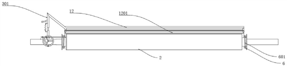
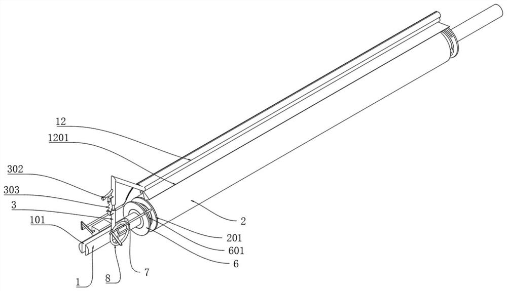
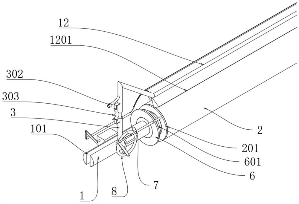
[0028] Refer to attached Figure 1-7 , a non-woven cloth winding cylinder for mask production, including a shaft 1, a rotating drum 2 is installed on the shaft 1 through a rotating sleeve 5, and the rotating drum 2 is used to clamp and place the cloth winding roller, and the cloth winding roller is placed on the rotating drum 2 Rotate up and transport the non-woven fabric to another set of winding drums;

[0029] In order to enable the cloth to be atomized and humidified when the cloth is discharged from the cl...


PUM


Abstract

The invention relates to a non-woven fabric winding barrel for mask production, which comprises a shaft rod, wherein a rotating barrel is mounted on the shaft rod through a rotating sleeve, a swinging barrel is arranged at the end part of the shaft rod, a tube part capable of ascending and descending is slidably inserted into the swinging barrel, a connecting tube connected to a tube orifice of an external humidifier penetrates through a tube part, and a humidifying rod is arranged on the tube part in the axis direction of the rotating barrel; the humidifying rod is positioned at the top of the rotating barrel; the rotating sleeve is in clearance fit to the shaft rod, a flow channel is formed in an inner layer cavity of the rotating barrel, a steel ball is arranged in the flow channel; when the rotating barrel rotates, the steel ball slides to the other end of the flow channel cavity from one end of the flow channel cavity, and when the cloth winding barrel rotates along with a cloth winding roller, centrifugal force can be generated, so that the steel ball moves to the other end of the cloth winding barrel from one end of the cloth winding barrel, and the cloth winding barrel can move on the shaft rod, and therefore, the cloth winding barrel can be guaranteed to drive a cloth roller to form cutting with discharged moisture, the moisture can act on the cloth cover more thoroughly, the humidifying effect is further improved, and the static electricity removing effect is better.

Description

technical field [0001] The invention relates to the technical field of cloth wrapping, in particular to a nonwoven cloth wrapping cylinder for mask production. Background technique [0002] During the production of masks, it is necessary to use the cloth winding drum to transfer the non-woven fabric to the production equipment. The production equipment is equipped with a guide roller for receiving the non-woven fabric, so the cloth winding drum used for the mask equipment is mostly a cloth feeding drum. , is to transport the non-woven fabric into a roll to the mask equipment, cut the non-woven fabric, suppress the folds, and finally obtain the mask we wear. This invention is aimed at the design of the arrangement-type winding drum. [0003] However, due to the thin texture of non-woven fabrics, which are mostly thin sheets of a few tenths of a millimeter, friction will be generated during transmission. As we all know, friction will generate static electricity. When non-woven...

Claims


Application Information

Patent Timeline
IPC IPC(8): B65H18/10D06B1/02
CPCB65H18/10D06B1/02
Inventor 刘永刚
Owner 江西艾酷玩具有限公司
Why Eureka
Try Eureka