
Unmanned aerial vehicle landing charging device and unmanned aerial vehicle system

A charging device and unmanned aerial vehicle technology, applied in the field of unmanned aerial vehicles, can solve the problems of being susceptible to environmental disturbance, slipping off of unmanned aerial vehicles, poor contact of contacts, etc., and meet the requirements of preventing slipping or poor contact of contacts and reducing structure , the effect of improving charging efficiency

Active Publication Date: 2021-05-04
PENG CHENG LAB
View PDF10 Cites 4 Cited by
  • Summary
  • Abstract
  • Description
  • Claims
  • Application Information

AI Technical Summary

Problems solved by technology

[0003] At present, an important factor limiting the further development of drones is battery life. At present, multi-rotor drones mostly use fast and timely charging to improve battery life and work efficiency. Therefore, it is necessary to set up a special device for docking and charging. Most of them are manually placed on the designated charging device, and the charging cable is manually connected to charge, which is inefficient and poor in autonomy
Some also use a flat grid charging board for wireless charging. The charging board is evenly divided into a number of mutually insulated grids. The charging contact of the drone will be charged after contacting it. However, this method does not have a fixed limit mechanism. Outdoors When used on a mobile platform (moving car, surface boat, etc.), it is easily disturbed by the environment, causing the UAV to slip or poor contact, which affects charging efficiency and battery life

Method used


Image

  • Unmanned aerial vehicle landing charging device and unmanned aerial vehicle system
  • Unmanned aerial vehicle landing charging device and unmanned aerial vehicle system
  • Unmanned aerial vehicle landing charging device and unmanned aerial vehicle system

Examples


Embodiment Construction

[0033] The following will clearly and completely describe the technical solutions in the embodiments of the present invention with reference to the accompanying drawings in the embodiments of the present invention. Obviously, the described embodiments are only part of the embodiments of the present invention, not all of them. Based on the embodiments of the present invention, all other embodiments obtained by persons of ordinary skill in the art without creative efforts fall within the protection scope of the present invention.

[0034] It should be noted that all directional indications (such as up, down, left, right, front, back...) in the embodiments of the present invention are only used to explain the relationship between the components in a certain posture (as shown in the accompanying drawings). Relative positional relationship, movement conditions, etc., if the specific posture changes, the directional indication will also change accordingly.

[0035] In the present in...


PUM


Abstract

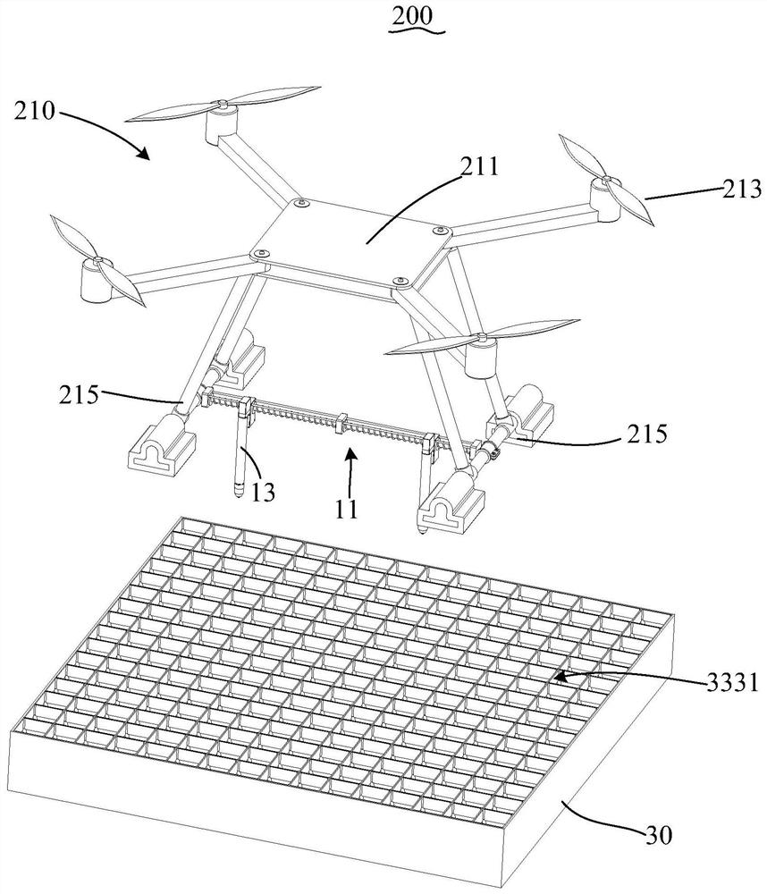
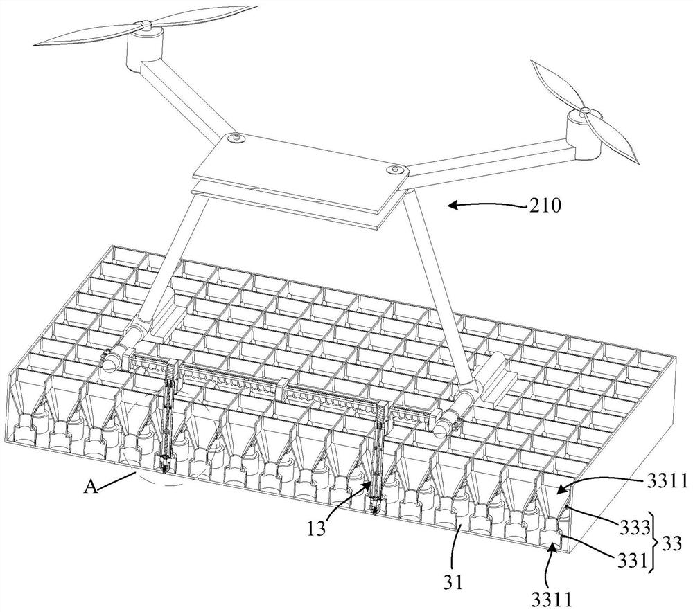
The invention discloses an unmanned aerial vehicle landing charging device and an unmanned aerial vehicle system. The unmanned aerial vehicle landing charging device comprises a charging rod assembly and a charging platform; the charging rod assembly comprises a support and at least two charging rods connected with the support; two free end parts of the two charging rods are respectively a positive charging contact and a negative charging contact; the charging platform comprises a charging panel and a fixing structure arranged on the surface of the charging panel; and the two charging rods are detachably connected to the fixing structure and electrically connected with the charging panel. According to the technical scheme, the unmanned aerial vehicle landing charging device can achieve anti-slip charging and is wide in applicability.

Description

technical field [0001] The invention relates to the technical field of unmanned aerial vehicles, in particular to an unmanned aerial vehicle landing charging device and an unmanned aerial vehicle system. Background technique [0002] Unmanned aircraft (Unmanned Aerial Vehicle, UAV) is an unmanned aircraft controlled by radio remote control equipment and self-contained program control device, because of its low cost, convenient use, mobility and flexibility Advantages, it is widely used in aerial photography, agriculture, plant protection, micro selfie, express transportation, military reconnaissance and other fields. Among them, multi-rotor drones are the most widely used. [0003] At present, an important factor limiting the further development of drones is battery life. At present, multi-rotor drones mostly use fast and timely charging to improve battery life and work efficiency. Therefore, it is necessary to set up a special device for docking and charging. Most of them ...

Claims


Application Information

Patent Timeline
Patent Type & Authority Applications(China)
IPC IPC(8): B60L53/30B60L53/16B64F1/00B64F1/12
CPCB60L53/30B60L53/16B64F1/00B64F1/125B60L2200/10Y04S30/12
Inventor 杨玉亮陆海博张卫东李胜全张爱东黄裘俊
Owner PENG CHENG LAB
Learn More