
Double-table vibration test device

A technology of vibration test and vibration device, which is applied in the direction of vibration test, measuring device, machine/structural component test, etc. It can solve problems such as unsure fixation, downhole tools easy to overturn, easily damaged ball head and vibration table, etc.

Inactive Publication Date: 2021-04-30
INST OF GEOLOGY & GEOPHYSICS CHINESE ACAD OF SCI
View PDF12 Cites 0 Cited by
  • Summary
  • Abstract
  • Description
  • Claims
  • Application Information

AI Technical Summary

Problems solved by technology

For the vibration test of downhole tools, the commonly used method at present is to directly fix the instrument under test on the vibration table through fixtures for vibration test. Since the downhole tool and the vibration table are connected by a ball head, the ball head is a movable structure with a certain deflection angle. Therefore, the downhole tool cannot be stably fixed on the vibration table after being connected by the fixture and the ball head, so there is a risk that the downhole tool is easy to overturn; in addition, during the vibration test, if the design test conditions are greater than the bearing capacity of the ball head or the vibration table It is easy to damage the ball head and the vibrating table. For the curved downhole tool, it cannot be guaranteed to be kept in a horizontal plane with the vibrating table, that is, the ball head has a deflection angle, and it is easy to damage the ball head and the vibrating table during the vibration test.

Method used


Image

  • Double-table vibration test device
  • Double-table vibration test device
  • Double-table vibration test device

Examples


Embodiment Construction

[0021] In order to make the object, technical solution and advantages of the present invention clearer, the present invention will be further described in detail below in combination with specific embodiments and with reference to the accompanying drawings. It should be understood that these descriptions are exemplary only, and are not intended to limit the scope of the present invention. Also, in the following description, descriptions of well-known structures and techniques are omitted to avoid unnecessarily obscuring the concept of the present invention.

[0022] A schematic structural diagram according to an embodiment of the present invention is shown in the accompanying drawings. The figures are not drawn to scale and certain details may have been omitted for the sake of clarity. The various regions, shapes, and their relative sizes and positional relationships shown in the figure are only exemplary, and may deviate due to manufacturing tolerances or technical limitatio...


PUM


Abstract

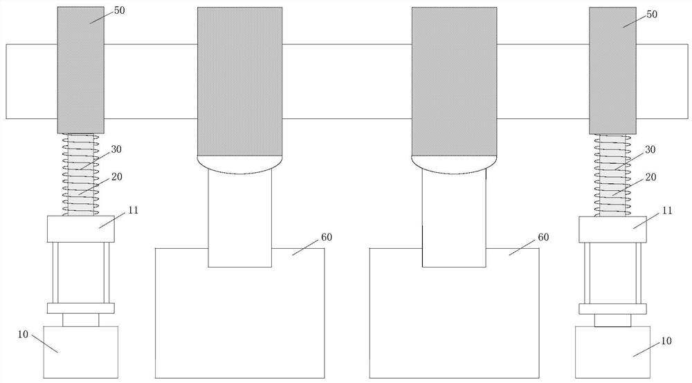
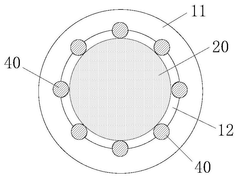
The invention provides a double-table vibration test device. The double-table vibration test device comprises two auxiliary devices and two vibration devices; each auxiliary device comprises a lifting device and a sliding part; the lifting device is provided with a lifting part; the sliding part is assembled on the lifting part, and the sliding part slides relative to the lifting part in the longitudinal direction; a drilling tool (an object to be tested) is lifted by the two auxiliary devices, so that the weight of the drilling tool does not exceed the maximum bearing capacity of a vibration device, the vibration device is not easy to damage, and the drilling tool is not easy to overturn in the vibration test process.

Description

technical field [0001] The invention relates to the technical field of downhole tool vibration tests, in particular to a double-stage vibration test device. Background technique [0002] The intelligent drilling guide system is a relatively advanced drilling and logging tool in the petroleum field at present. When working in the downhole, it faces a working environment with strong vibration and strong impact. Vibration simulation test to verify the environmental adaptability and reliability of the instrument. For the vibration test of downhole tools, the commonly used method at present is to directly fix the instrument under test on the vibration table through fixtures for vibration test. Since the downhole tool and the vibration table are connected by a ball head, the ball head is a movable structure with a certain deflection angle. Therefore, the downhole tool cannot be stably fixed on the vibration table after being connected by the fixture and the ball head, so there is...

Claims


Application Information

Patent Timeline
IPC IPC(8): G01M7/02
CPCG01M7/02
Inventor 裴仁忠王中兴张文秀张天信杨永友赵丹
Owner INST OF GEOLOGY & GEOPHYSICS CHINESE ACAD OF SCI
Learn More