
Piling device for constructional engineering and piling device connecting structure

A piling device and construction engineering technology, which is applied in construction, foundation structure engineering, sheet pile walls, etc., can solve the problems that the soil on the pile cannot be shaken off, is not fast enough, and the installation of the pile is cumbersome, etc., and achieves the effect of preventing bump damage

Pending Publication Date: 2021-04-30
叶华攀
View PDF8 Cites 1 Cited by
  • Summary
  • Abstract
  • Description
  • Claims
  • Application Information

AI Technical Summary

Problems solved by technology

[0007] In order to solve the above technical problems, the present invention provides a piling device for construction engineering and a connection structure of the piling device to solve the existing problem that the existing device cannot simultaneously realize the automatic cleaning of the soil on the pile shaft during piling, and with this At the same time, it is impossible to shake off the soil on the pile pole through structural improvement; moreover, the pile pole of the existing device is more cumbersome and not fast enough during installation, and it is impossible to realize the rapid installation of the pile pole through structural improvement and when it is placed. The problem of effective protection

Method used


Image

  • Piling device for constructional engineering and piling device connecting structure
  • Piling device for constructional engineering and piling device connecting structure
  • Piling device for constructional engineering and piling device connecting structure

Examples


Embodiment

[0033] as attached figure 1 to attach Figure 7 Shown:

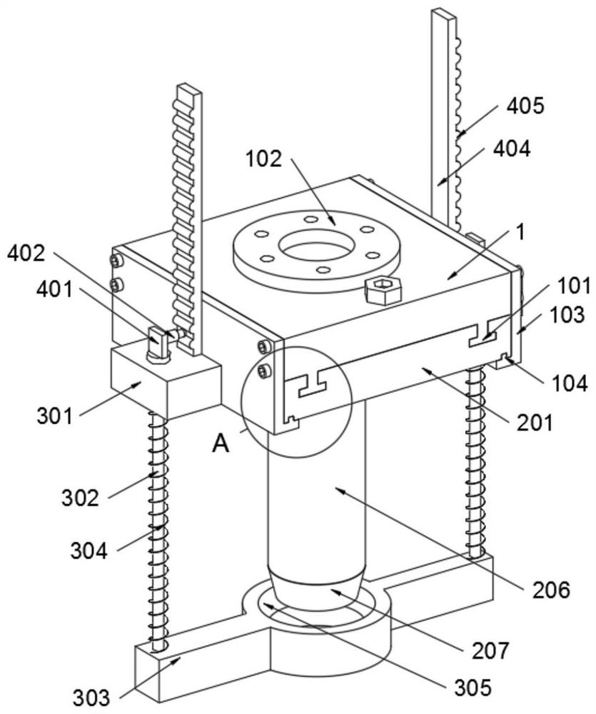
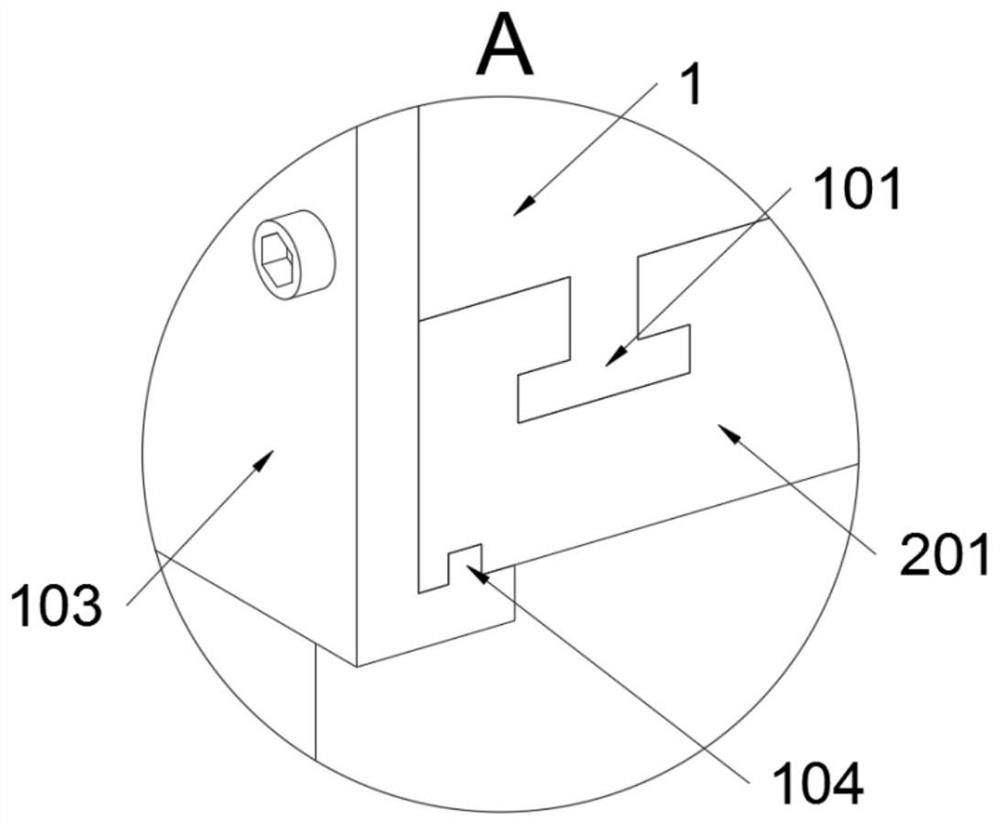
[0034] The invention provides a piling device for construction engineering and a connection structure of the piling device, including a mounting base 1; a pile structure 2 is installed on the mounting base 1, and a cleaning structure 3 is installed on the mounting base 1; Auxiliary structure 4 is installed; refer to e.g. Figure 4 , the mounting base 1 includes a connecting plate 103, two connecting plates 103 are provided, and the two connecting plates 103 are fixedly connected to the mounting base 1 by bolts, and the two connecting plates 103 are L-shaped structures; the connecting plate 103 The inner wall is in contact with the outside of the connecting seat A201, and the two connecting plates 103 jointly form the auxiliary fixing structure of the connecting seat A201; The protective structure of the snap-in protrusion A101 is formed, so that the snap-in protrusion A101 can be prevented from being bumped and damage...


PUM


Abstract

The invention provides a piling device for constructional engineering and a piling device connecting structure, and relates to the technical field of construction machinery. The problems that automatic cleaning of soil on a pile rod cannot be synchronously realized, meanwhile, shaking-off of the soil on the pile rod cannot be realized through structural improvement, and rapid installation of the pile rod and effective protection during placement cannot be achieved through structural improvement are solved. The piling device for constructional engineering and the piling device connecting structure comprises a mounting base, wherein a pile rod structure is mounted on the mounting base, a cleaning structure is further mounted on the mounting base, and an auxiliary structure is further mounted on the mounting base. The inner walls of connecting plates are in contact with the outer side of connecting seat A, and the two connecting plates jointly form an auxiliary fixing structure of the connecting seat A; the bottom end faces of the connecting plates are lower than the bottom end faces of clamping protrusions A, the two connecting plates further form a protection structure of the clamping protrusions A, and therefore the clamping protrusions A can be prevented from being collided and damaged during placement.

Description

technical field [0001] The invention belongs to the technical field of construction machinery, and more specifically relates to a piling device for construction engineering and a connection structure of the piling device. Background technique [0002] The construction method of smashing wooden piles or stone piles into the ground, and using special machines to drive, press, vibrate or screw piles of various materials into the foundation soil in order to make the foundation of the building firm. [0003] For example, the application number: CN201811256099.6, the present invention discloses a piling device, which includes a chassis assembly, a piling assembly and a traction assembly. The chassis assembly includes a base, an internal gear, a rotating motor, a stabilizing claw and a bottom plate. The internal gear is meshed with the base, the internal gear is located inside the base, and the output shaft of the rotating motor is meshed with the internal gear; Clutch plate, the ...

Claims


Application Information

Patent Timeline
IPC IPC(8): E02D7/00B08B7/02
CPCE02D7/00B08B7/02
Inventor 叶华攀
Owner 叶华攀
Learn More