
Motor braking speed reduction equipment for electric scooter based on new energy

An electric scooter and motor braking technology, applied in the direction of brakes, braking components, vehicle parts, etc., can solve the problems of inability to brake the car body, inability to remind passing vehicles and pedestrians, and drivers forgetting to whistle reminders, etc. The effect of braking avoidance

Inactive Publication Date: 2021-04-30
贺国庆
View PDF0 Cites 2 Cited by
  • Summary
  • Abstract
  • Description
  • Claims
  • Application Information

AI Technical Summary

Problems solved by technology

[0002] At present, with the popularization of new energy technology and in order to implement the concept of energy saving and environmental protection, more and more users will choose electric scooters for travel. The user cannot safely and effectively brake the car body, and the corresponding car body will automatically slide due to inertia, resulting in an accident. In addition, when the car body loses its brakes, the driver will forget to whistle due to panic Unable to remind passing vehicles and pedestrians to pay attention
[0003] Aiming at the deficiencies of the prior art, the present invention provides a new energy-based motor brake deceleration device for electric scooter, which can safely and effectively brake the car body to avoid accidents, and effectively remind passing vehicles and pedestrians to avoid It solves the problem that the general electric scooter cannot safely and effectively brake the car body when the brake system fails, and the driver will forget to whistle to remind him because of panic.

Method used


Image

  • Motor braking speed reduction equipment for electric scooter based on new energy
  • Motor braking speed reduction equipment for electric scooter based on new energy
  • Motor braking speed reduction equipment for electric scooter based on new energy

Examples


Embodiment Construction

[0021] The following will clearly and completely describe the technical solutions in the embodiments of the present invention with reference to the accompanying drawings in the embodiments of the present invention. Obviously, the described embodiments are only some, not all, embodiments of the present invention. Based on the embodiments of the present invention, all other embodiments obtained by persons of ordinary skill in the art without making creative efforts belong to the protection scope of the present invention.

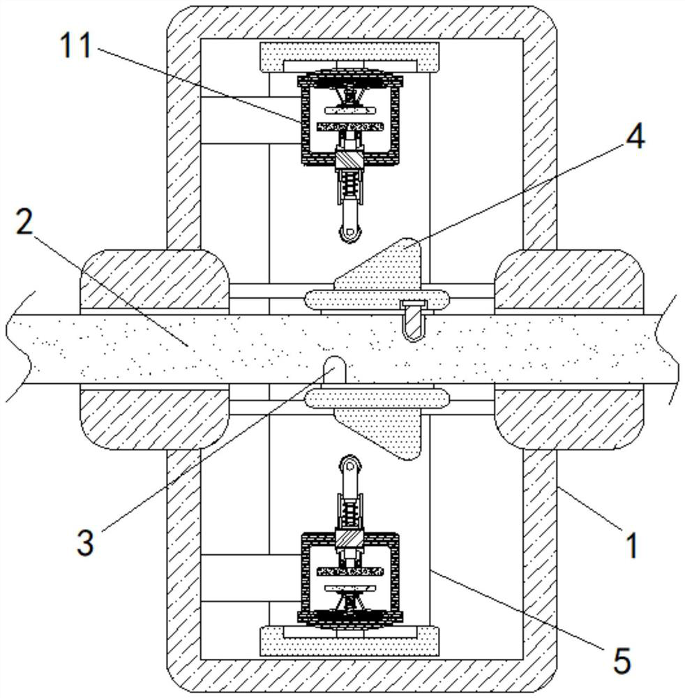
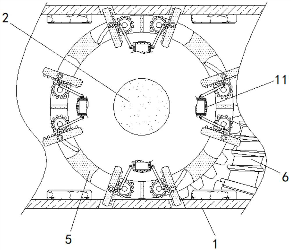
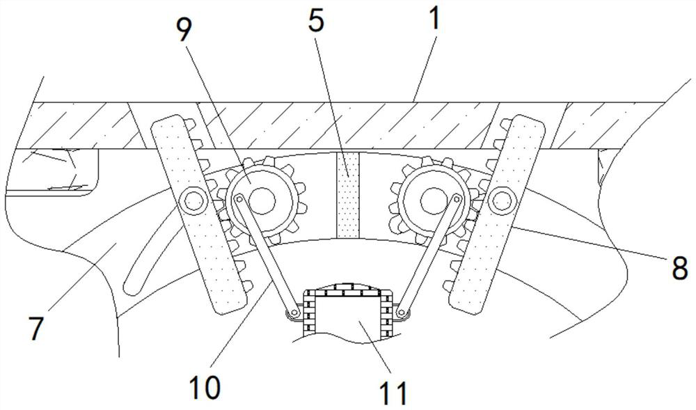
[0022] see Figure 1-5 , a motor braking deceleration device for electric scooter based on new energy, comprising a housing 1, the middle part of the housing 1 is rotatably connected to an output shaft 2, the surface of the output shaft 2 is provided with a ring groove 3, and the inner part of the housing 1 The middle part of the cavity is slidingly connected with a special-shaped ring 4 sleeved on the output shaft 2, and the inner cavity side wall of the spec...


PUM


Abstract

The invention relates to the technical field of motors, and discloses motor brake deceleration equipment for an electric scooter based on new energy, which comprises a shell, an output shaft is rotatably connected to the middle of the shell, an annular groove is formed in the surface of the output shaft, and a special-shaped ring connected to the output shaft in a sleeving mode is slidably connected to the middle of an inner cavity of the shell. An inner cavity of the shell is rotationally connected with an adjusting ring, and the front portion of the inner cavity of the shell is rotationally connected with an adjusting worm extending to the adjusting ring. According to the motor braking speed reduction equipment for the electric scooter based on the new energy, an adjusting worm is driven by an external drive to enable an adjusting ring to deflect, a protection frame drives an elastic speed reduction rod to get close to a special-shaped ring, an output shaft is matched to rotate depending on inertia and drive the special-shaped ring to reciprocate, and the special-shaped ring intermittently extrudes the elastic speed reduction rod; therefore, the vehicle body is safely and effectively braked, accidents are avoided, and passing vehicles and pedestrians are effectively reminded to avoid.

Description

technical field [0001] The invention relates to the technical field of motors, in particular to a new energy-based motor braking and deceleration device for electric scooter. Background technique [0002] At present, with the popularization of new energy technology and in order to implement the concept of energy saving and environmental protection, more and more users will choose electric scooters for travel. The user cannot safely and effectively brake the car body, and the corresponding car body will automatically slide due to inertia, resulting in an accident. In addition, when the car body loses its brakes, the driver will forget to whistle due to panic It is impossible to remind passing vehicles and pedestrians to pay attention. [0003] Aiming at the deficiencies of the prior art, the present invention provides a new energy-based motor brake deceleration device for electric scooter, which can safely and effectively brake the car body to avoid accidents, and effectivel...

Claims


Application Information

Patent Timeline
Patent Type & Authority Applications(China)
IPC IPC(8): B60T1/06B60Q5/00
CPCB60Q5/00B60T1/062
Inventor 贺国庆
Owner 贺国庆
Learn More