
An integrated concrete pouring and vibrating machine for composite floor slabs of an assembled integral building

A technology for laminated slabs and concrete, which is applied in the direction of supply devices, ceramic molding machines, manufacturing tools, etc., can solve the problems of poor concrete fluidity, concrete air bubbles, and affecting the pouring quality of laminated slabs, so as to reduce equipment costs and eliminate air bubbles , Improve the effect of the scope of use

Active Publication Date: 2022-02-15
新疆天筑建工集团有限公司
View PDF10 Cites 0 Cited by
  • Summary
  • Abstract
  • Description
  • Claims
  • Application Information

AI Technical Summary

Problems solved by technology

The laminated slab has good integrity and high rigidity, which can save templates, and the upper and lower surfaces of the slab are flat, which is convenient for decoration of the facing layer. It is suitable for high-rise buildings and large-bay buildings that require high overall rigidity. It is used in the concrete pouring production of laminated floors Usually, concrete is poured into formwork moldings. Since the size of the building requires the same parts, the size of the concrete prefabricated floor slabs required is also different. During the pouring work, due to the poor fluidity of the concrete, it is difficult to , there will be air bubbles in the concrete after pouring, which will affect the pouring quality of the laminated slab. Therefore, it is necessary to design an integrated concrete pouring and vibrating machine for the laminated floor of an assembled building to solve the above problems.

Method used


Image

  • An integrated concrete pouring and vibrating machine for composite floor slabs of an assembled integral building
  • An integrated concrete pouring and vibrating machine for composite floor slabs of an assembled integral building
  • An integrated concrete pouring and vibrating machine for composite floor slabs of an assembled integral building

Examples


Embodiment approach

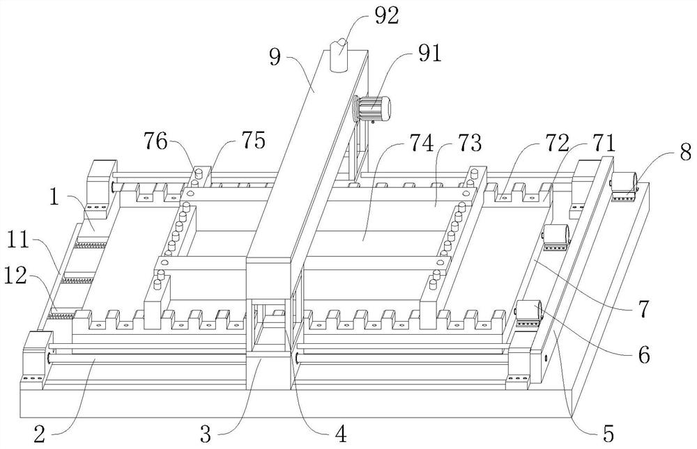
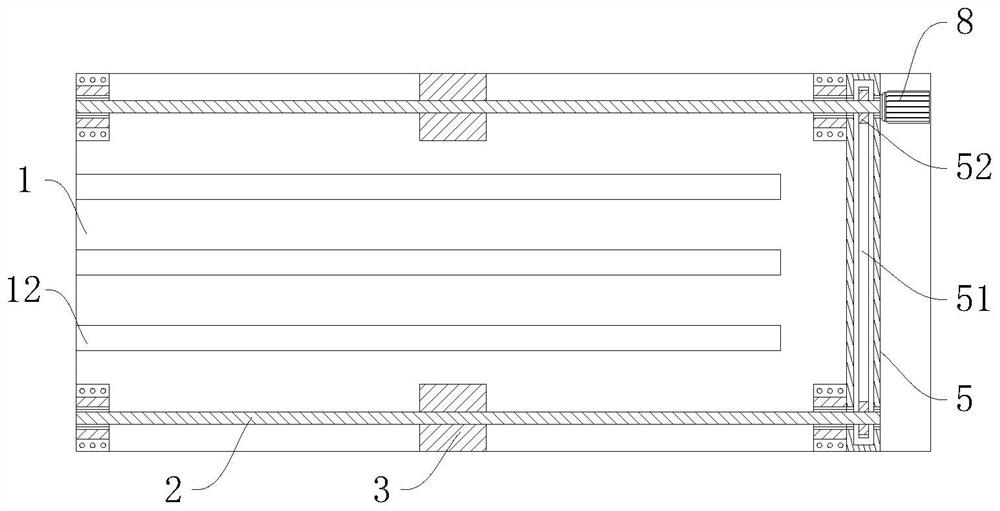
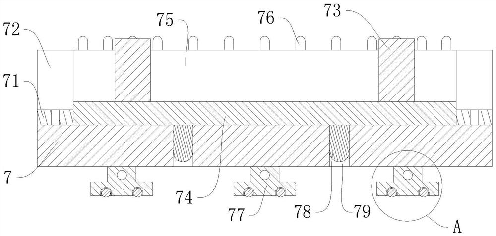
[0032] The specific embodiment, at first connect the circuit of vibrating machine 6, the first driver 8 and the second driver 91, and select the bottom formwork 74 of suitable specification, then the bottom formwork 74 is placed on the workbench plate 7 upper end, and utilize the first Two positioning columns 78 and the first positioning through hole 79 are used to position and install the bottom template 74 and the worktable 7, and then the transverse horizontal plate 75 is snapped into the corresponding adjustment slots 72 on the two support plates 71, and then Two horizontal horizontal plates 75 are installed on the workbench 7 by adjusting the draw-in groove 72. At this time, the two horizontal horizontal plates 75 are at the left and right ends of the bottom template 74, and then the vertical parts of the two T-shaped longitudinal templates 73 Both are inserted between the two transverse horizontal plates 75, and then the T-shaped longitudinal template 73 is attached to th...


PUM


Abstract

The present invention relates to the technical field of prefabricated building floor slab production, in particular to a concrete pouring and vibrating integrated machine for assembling integral building laminated slabs, including a base plate, a screw rod, a nut seat, a support frame, a protection box, a vibrator, The worktable, the first driving machine and the pouring box drive the two screw rods to rotate synchronously through the first driving machine, the chain and the two sprockets, and under the action of the ball nut, the two nut seats are driven left and right along the base plate Move, and then drive the two support frames to move left and right, so that the pouring box moves left and right directly above the forming formwork, and then use the pouring box to pour concrete into the forming formwork. After the pouring is completed, the vibrator is used to drive the workbench The slab vibrates left and right on the top of the base plate, so as to vibrate the concrete poured in the formed formwork, effectively eliminate the air bubbles in the concrete after pouring, improve the pouring quality of the laminated floor, and realize the integrated design of pouring and vibration, reducing equipment cost.

Description

technical field [0001] The invention relates to an integrated concrete pouring and vibrating machine for an assembled integral building laminated floor slab, which belongs to the technical field of assembly building floor slab production. Background technique [0002] The laminated slab is an assembled monolithic building slab formed by laminating prefabricated slabs and cast-in-place reinforced concrete layers. The prefabricated slab is not only one of the components of the floor structure, but also a permanent formwork for the cast-in-place reinforced concrete laminated layer. Horizontal equipment pipelines can be laid in the cast-in-place laminated layer. The laminated slab has good integrity and high rigidity, which can save templates, and the upper and lower surfaces of the slab are flat, which is convenient for decoration of the facing layer. It is suitable for high-rise buildings and large-bay buildings that require high overall rigidity. It is used in the concrete po...

Claims


Application Information

Patent Timeline
Patent Type & Authority Patents(China)
IPC IPC(8): B28B1/04B28B1/29B28B13/02
CPCB28B1/045B28B1/29B28B13/02
Inventor 李成翠廖瑜琳
Owner 新疆天筑建工集团有限公司
Learn More