Rotatable and deformable suspension device for intelligent household appliance
A suspension device and home appliance technology, applied in tool storage devices, manufacturing tools, etc., can solve problems such as single function and non-adjustable suspension angle
- Summary
- Abstract
- Description
- Claims
- Application Information
AI Technical Summary
Problems solved by technology
Method used
Image

Examples
Embodiment 1
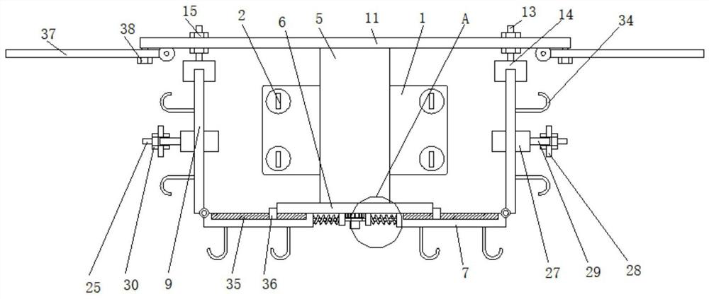
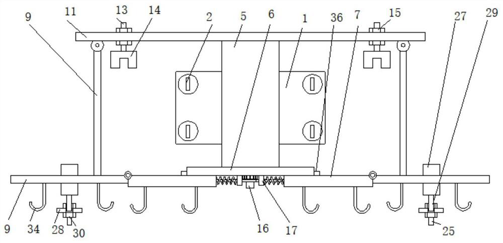
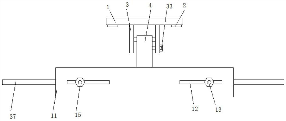
[0032] Embodiment one, such as Figure 1-9As shown, a rotatable and deformable suspension device for smart home appliances includes a vertically arranged fixed plate 1. The fixed plate 1 is fixedly connected to the wall through a plurality of mounting screws 2. The fixed plate 1 is fixedly connected with two vertically arranged The first connecting plate 3, the second connecting plate 4 is arranged between the two first connecting plates 3, the two first connecting plates 3 are connected with the second connecting plate 4 in rotation, the second connecting plate 4 is away from the first connecting plate One end of the plate 3 is fixedly connected with a third connecting plate 5, and the bottom end of the third connecting plate 5 is fixedly connected with a horizontal connecting plate 6, and the bottom surface of the connecting plate 6 is slidably connected with two horizontally arranged sliding plates 7, and the two sliding plates 7 Symmetrically arranged, a moving mechanism 8...
Embodiment 2
[0033] Embodiment two, such as figure 1 , 2 , 5, and 8, the moving mechanism 8 includes a vertical fixed column 16, the fixed column 16 is rotatably connected to the bottom surface of the connecting plate 6, the connecting plate 6 is located between the two sliding plates 7, and both sides of the fixed column 16 are vertical. A baffle 17 is provided, and the two baffles 17 are all fixedly connected to the bottom surface of the connecting plate 6, and the two baffles 17 are all located between the two sliding plates 7, and the two sliding plates 7 pass through the horizontal first spring 18 and the The baffle plate 17 corresponding to the same side is fixedly connected, and the two sliding plates 7 are fixedly connected to the fixed column 16 through the steel wire rope 19 respectively, and the two steel wire ropes 19 are both wound on the fixed column 16, and the two steel wire ropes 19 respectively run through the corresponding baffle plate on the same side 17 and slidably c...
Embodiment 3
[0034] Embodiment three, such as Figure 5 , 9 As shown, the fixed column 16 is fixedly connected with a horizontally arranged gear 20, and one side of the fixed column 16 is vertically provided with an abutment plate 21 fixedly connected to the bottom surface of the connecting plate 6, and a clamping member 22 is arranged between the abutment plate 21 and the gear 20 , the clamping piece 22 is T-shaped, the clamping piece 22 is in contact with the gear 20, the clamping piece 22 is fixedly connected to the abutment plate 21 through a horizontally arranged telescopic rod 23, and the clipping piece 22 is fixedly connected to the abutment plate 21 through a horizontally arranged second spring 24 It is fixedly connected with the support plate 21, the second spring 24 is wound on the telescopic rod 23, and the gear 20 is limited by setting the clip 22, so that the rotation of the fixed column 16 is controllable, and the clip is connected by the second spring 24 22 and the baffle 1...
PUM
 Abstract
Description
Claims
Application Information
 - R&D
- Intellectual Property
- Life Sciences
- Materials
- Tech Scout
- Unparalleled Data Quality
- Higher Quality Content
- 60% Fewer Hallucinations
Browse by: Latest US Patents, China's latest patents, Technical Efficacy Thesaurus, Application Domain, Technology Topic, Popular Technical Reports.
© 2025 PatSnap. All rights reserved.Legal|Privacy policy|Modern Slavery Act Transparency Statement|Sitemap|About US| Contact US: help@patsnap.com