
Centrifuge tube suction filtration device

A suction filtration device and centrifuge tube technology, applied in the field of suction filtration, can solve the problems of loss, cross-contamination of samples, and complicated operation.

Active Publication Date: 2021-04-30
GUANGDONG TESTING INST OF PROD QUALITY SUPERVISION
View PDF14 Cites 0 Cited by
  • Summary
  • Abstract
  • Description
  • Claims
  • Application Information

AI Technical Summary

Problems solved by technology

[0002] The suction filtration device in the prior art mainly includes: filter cup, funnel, filter membrane, glass cover and suction filtration bottle, which is partially improved for the vacuum suction filtration device Or combined, to a certain extent, it improves the convenience of use and solves some shortcomings of the vacuum filtration device; however, it still has the problem that the suction filtration device is too large to perform suction filtration of a small volume of solution, the operation is cumbersome, and there are many steps. Defects such as large loss during solution transfer
[0003] At present, the sample filtration steps of the traditional suction filtration device are generally as follows: the sample is poured into the filter cup, enters the suction filter bottle through the filter membrane, and then transfers from the suction filter bottle to the sample bottle, this process requires at least two sample transfers, which increases the loss and possible cross-contamination of the sample filtration process, and the suction filtration of a small volume of solution is easy to cause sample loss and cross-contamination
[0004]Based on this, it is necessary to design a suction filtration device that directly realizes the intercommunication of samples in two centrifuge tubes, so as to solve the possible cross-contamination while saving pouring liquid and transferring liquid The problem

Method used


Image

  • Centrifuge tube suction filtration device
  • Centrifuge tube suction filtration device
  • Centrifuge tube suction filtration device

Examples


Embodiment 1

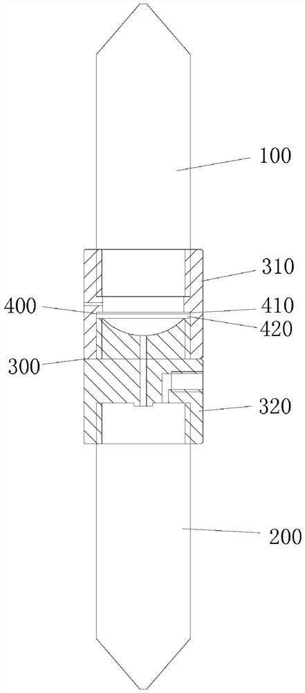
[0042] This embodiment provides a centrifuge tube suction filtration device, such as Figure 1-6 As shown, it includes a first centrifuge tube 100, a second centrifuge tube 200, a connection assembly 300 and a filter assembly 400, wherein the first centrifuge tube 100 and the second centrifuge tube 200 are connected through the connection assembly 300, and the filter assembly 400 is assembled on the connection within the assembly 300.

[0043] Wherein the connecting assembly 300 includes a first connecting seat 310 and a second connecting seat 320 connected to each other, the first connecting seat 310 is detachably connected with the first centrifuge tube 100 as a whole, the second connecting seat 320 and the second centrifuge tube 200 can be detachably connected together;

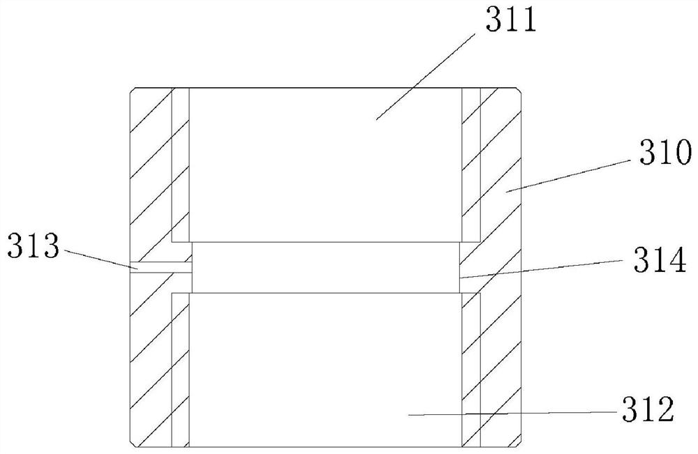
[0044] The first connection seat 310 is provided with a first connection groove 311 and a second connection groove 312, the second connection seat 320 is provided with a third connection groove 321 and a ...


PUM


Abstract

The invention provides a centrifuge tube suction filtration device which comprises a first centrifuge tube, a second centrifuge tube, a connecting assembly and a filtering assembly, and the first centrifuge tube is connected with the second centrifuge tube through the connecting assembly; the connecting assembly comprises a first connecting base and a second connecting base. The filtering assembly comprises a filtering membrane and a supporting plate, and the filtering membrane is arranged on the supporting plate; a first connecting groove and a second connecting groove are formed in the first connecting base, a third connecting groove and a connecting boss are arranged on the second connecting base, the first centrifugal tube is connected in the first connecting groove, the connecting boss can extend into the second connecting groove and press and fix the supporting plate, and the second centrifugal tube is connected in the third connecting groove; a vent hole communicated with the interior of the first centrifugal tube is formed in one side of the first connecting base, an air suction hole communicated with the interior of the second centrifugal tube is formed in one side of the second connecting base, and a through liquid guide pipe is arranged on the connecting boss; the centrifuge tube suction filtration device has the advantages of simple structure, convenient operation and replaceable filter membrane, and is especially suitable for suction filtration of a small volume of solution.

Description

technical field [0001] The invention belongs to the technical field of suction filtration, and in particular relates to a centrifugal tube suction filtration device. Background technique [0002] The suction filtration device in the prior art mainly includes: a filter cup, a funnel, a filter membrane, a glass cover and a suction filtration bottle, which is partially improved or combined with the vacuum suction filtration device, which improves the convenience of use to a certain extent and solves the problem of However, it still has defects such as the suction filtration device is too large, cannot perform suction filtration of a small volume of solution, the operation is cumbersome, there are many steps, and the loss in the solution transfer process is large. [0003] At present, the sample filtration steps of the traditional suction filtration device are generally as follows: the sample is poured into the filter cup, enters the suction filter bottle through the filter memb...

Claims


Application Information

Patent Timeline
IPC IPC(8): B01D29/05
CPCB01D29/05
Inventor 刘琼陈满英陈纪文包楚才冯艳梁英杰何勇
Owner GUANGDONG TESTING INST OF PROD QUALITY SUPERVISION
Learn More