Pre-expander and matching structure of pre-expander and vascular sheath device
A technology of coordinating structure and pre-expanding device, which is applied in the direction of dilators, catheters, medical devices, etc., can solve the problems of head injury of surgical instruments, affect the normal use of surgical instruments, and large resistance, so as to achieve the effect of improving adaptability
- Summary
- Abstract
- Description
- Claims
- Application Information
AI Technical Summary
Problems solved by technology
Method used
Image
Examples
Embodiment 1
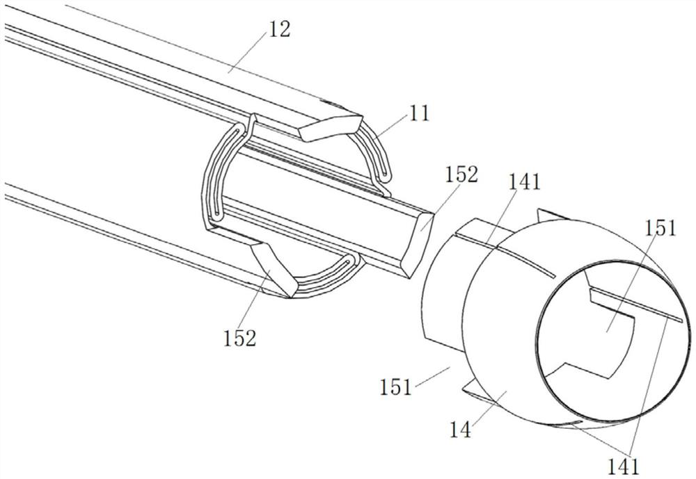
[0105] This embodiment provides a pre-spreader, such as Figure 13 As shown, the pre-expander includes a pre-expansion tube 31, and a second head 32 disposed on the far end of the pre-expansion tube 31, at least part of the outer diameter of the second head 32 is greater than that of the head cap of the expansion tube 1. The inner diameter of the distal end, the pre-expansion tube and the second head 32 are suitable for sliding in the expansion tube 1 to expand the head cap 14 of the expansion tube in the radial direction.
[0106] The pre-expander of this structure, because the outer diameter of at least part of the second head 32 is greater than the inner diameter of the distal end of the head cap 14 of the expansion tube 1, after the expansion tube 1 slides in place in the blood vessel, the pre-expander is used first. The pre-expansion tube and the second head 32 slide in the expansion tube 1, at least part of the second head 32 passes through the distal end of the head cap...
Embodiment 2
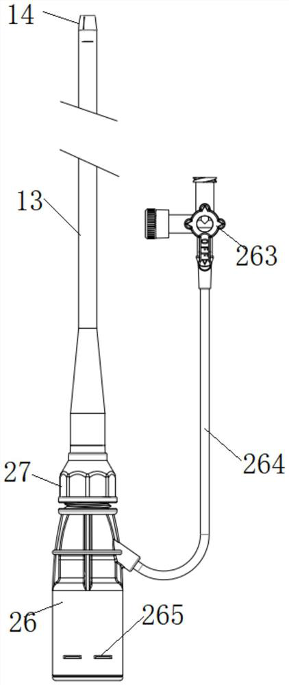
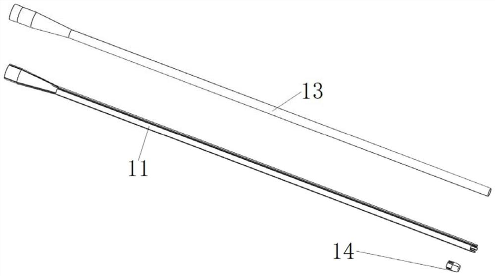
[0119] In this embodiment, a matching structure between a pre-expander and a vascular sheath device is provided, including the pre-expander and the vascular sheath device provided in Embodiment 1, such as Figure 1 to Figure 14 As shown, the vascular sheath device includes a housing 26 , a hemostatic valve 2 and a dilation tube 1 . Wherein, the hemostasis valve 2 is arranged on the opening of the proximal end of the housing 26 in a sealed manner; the proximal end of the expansion tube 1 is installed on the opening of the distal end of the housing 26 .
[0120] For example, if Figure 5a , Figure 5b and Figure 11 As shown, the above-mentioned locking part is a locking cap, and the outer wall surface of the opening at the far end of the housing 26 has external threads, the opening at the proximal end of the expansion tube is fixed with a fixing ring 28, and the distal end of the housing 26 is threaded with a lock Tight cap, the near end of fixing ring 28 is flared structure...
Embodiment 3
[0197] The embodiment of the present invention provides a matching structure of the pre-dilator and the vascular sheath device, which is different from the matching structure provided in Example 2 in that:
[0198]The structure of the expansion tube in the vascular sheath device is different. Specifically, the expansion tube does not include the installation part 12, but only includes the deformation part 11, and the deformation part 11 may be one, two, or more. When the deformation part 11 is one, the first end 111 and the second end 112 of the deformation part 11 form a closed loop. is stretched to change its bore diameter. When there are multiple deformed parts 11, the first end 111 of any two adjacent deformed parts 11 is connected to the second end 112 of another deformed part to form an annular pipe, and the expansion pipe is formed by deformed parts 11 along its circumference. , to further increase the radial deformation of the expansion tube.
[0199] As a modificati...
PUM
 Abstract
Description
Claims
Application Information
 - R&D
- Intellectual Property
- Life Sciences
- Materials
- Tech Scout
- Unparalleled Data Quality
- Higher Quality Content
- 60% Fewer Hallucinations
Browse by: Latest US Patents, China's latest patents, Technical Efficacy Thesaurus, Application Domain, Technology Topic, Popular Technical Reports.
© 2025 PatSnap. All rights reserved.Legal|Privacy policy|Modern Slavery Act Transparency Statement|Sitemap|About US| Contact US: help@patsnap.com


