Modified asphalt mixing equipment and mixing method thereof

A modified asphalt and equipment technology, applied in the field of modified asphalt mixing equipment, can solve problems such as waste, waste heat not recovered, and increased processing costs

Inactive Publication Date: 2021-04-27
襄阳路桥建设集团有限公司
View PDF5 Cites 0 Cited by
  • Summary
  • Abstract
  • Description
  • Claims
  • Application Information

AI Technical Summary

Problems solved by technology

However, in the prior art, since the asphalt needs to be mixed with the aggregate at a relatively high temperature, the operation of the mixing equipment needs to consume a large amount of energy when adding asphalt, and there is a serious waste of a large amount of energy, which is manifested as Waste heat is not recovered, resulting in waste, increased processing costs, etc. At the same time, there is no targeted treatment for the generated flue gas, resulting in environmental pollution
In addition, for different asphalt, such as modified asphalt, petroleum asphalt, etc., the mixing conditions (such as temperature) are not the same, and the temperature is too high and it is easy to age. Therefore, for different types of asphalt and asphalt at different mixing stages, it is necessary to The mixing bin is controlled in a targeted manner to ensure the quality of the asphalt mixture after mixing. However, the existing mixing equipment basically adopts a fixed mixing method, which makes it unable to meet the existing asphalt mixing requirements.

Method used


Image

  • Modified asphalt mixing equipment and mixing method thereof

Examples


Embodiment Construction

[0035] The principles and features of the present invention are described below in conjunction with the accompanying drawings, and the examples given are only used to explain the present invention, and are not intended to limit the scope of the present invention.

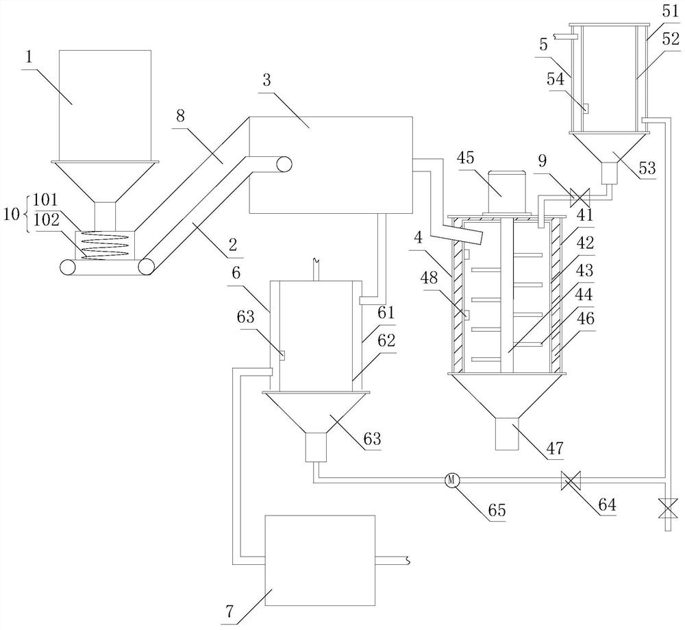
[0036] Such as figure 1 As shown, a mixing equipment for modified asphalt includes an aggregate bin 1, a lifting mechanism 2, a drying bin 3, a mixing bin 4, an asphalt bin 5, a heat exchange bin 6 and a dust removal mechanism 7, the aggregate bin 1 is set above the lower end of the lifting mechanism 2, the higher end of the lifting mechanism 2 communicates with the inlet of the drying bin 3, and the outlet of the drying bin 3 is connected to the One feed port of the mixing bin 4 communicates, the discharge port of the asphalt bin 5 communicates with another feed port of the mixing bin 4, and the liquid inlet of the heat preservation chamber of the asphalt bin 5 communicates with the The liquid outlet of the heat e...


PUM


Abstract

The invention relates to modified asphalt mixing equipment which comprises an aggregate bin, a lifting mechanism, a drying bin, a mixing bin, an asphalt bin, a heat exchange bin and a dust removal mechanism, aggregate in the aggregate bin is conveyed to the drying bin through the lifting mechanism, and a discharging port of the drying bin is communicated with a feeding port of the mixing bin; a discharging port of the asphalt bin is communicated with the other feeding port of the mixing bin, a liquid inlet of a heat preservation cavity of the asphalt bin is communicated with a liquid outlet of the heat exchange bin, the heat preservation cavity of the asphalt bin is communicated with the heat exchange bin, a transduction cavity of the heat exchange bin is communicated with the drying bin, and the transduction cavity of the heat exchange bin is communicated with the dust removal mechanism. Targeted heating and stirring are conducted through the mixing bin, meanwhile, high-temperature flue gas in the drying bin enters the heat exchange bin to heat heat exchange liquid, the heat exchange liquid is conveyed into the asphalt bin to heat and preserve heat of asphalt, repeated utilization of heat energy is achieved, energy is saved, the cost is reduced, and the flue gas is exhausted after being treated by the dust removal mechanism. and environmental pollution is avoided.

Description

technical field [0001] The invention relates to the technical field of asphalt construction, in particular to a modified asphalt mixing equipment and a mixing method thereof. Background technique [0002] With the continuous advancement of urban and rural infrastructure construction, asphalt is widely used as a convenient, efficient and durable material. When using asphalt, it needs to be mixed with aggregate, and it is most commonly used as a complete set of mixing equipment. The technology is relatively mature. However, in the prior art, since the asphalt needs to be mixed with the aggregate at a relatively high temperature, the operation of the mixing equipment needs to consume a large amount of energy when adding asphalt, and there is a serious waste of a large amount of energy, which is manifested as Waste heat is not recovered, resulting in waste and increased processing costs. At the same time, there is no targeted treatment for the generated flue gas, resulting in e...

Claims


Application Information

Patent Timeline
IPC IPC(8): E01C19/10
CPCE01C19/1013
Inventor 柯达卢红菊谢炳辉李兵吴洋
Owner 襄阳路桥建设集团有限公司
Why Eureka
Try Eureka