Lower knife rest device

The technology of a holder device and a tool holder is applied in the field of the lower tool holder device, which can solve the problems of increasing the gap between the cutting edges, the large seam, and the loose elasticity of the stud, and achieve the effect of reducing the friction force.

Active Publication Date: 2022-05-10
CHINA ERZHONG GRP DEYANG HEAVY IND
View PDF20 Cites 0 Cited by
  • Summary
  • Abstract
  • Description
  • Claims
  • Application Information

AI Technical Summary

Problems solved by technology

[0002] The top of the lower knife rest of the roll-cut double-sided shear is equipped with a lower knife rest guard. When feeding the plate, the sheet material slides and rubs on the lower knife rest guard. Every time the plate is fed, the lower knife rest guard will be worn. It will cause severe wear of the lower knife rest guard, reducing the service life of the lower knife rest guard
[0003] The lower knife rest and the frame in the rolling-cut double-sided shear are connected together by studs, and because the size and joint position of the studs are limited by the structural space of the equipment, when the steel plate is cut, there will be studs. The column is loose or elastically elongated, which leads to a gap between the joint surface between the lower tool holder and the frame, commonly known as seam; the greater the shear force, the greater the seam
A small seam start will increase the cutting edge clearance and affect the cutting quality, and a large seam start will damage the roll-cut double-sided shear

Method used


Image

  • Lower knife rest device
  • Lower knife rest device
  • Lower knife rest device

Examples


Embodiment Construction

[0028] In order to make those skilled in the art better understand the present invention, the present invention will be further described below in conjunction with the accompanying drawings and embodiments. Apparently, the described embodiments are only some of the embodiments of the present invention, but not all of them. In the case of no conflict, the embodiments and the features in the embodiments of the present invention can be combined with each other.

[0029] For the convenience of description, the "left" and "right" referred to below are consistent with the left and right directions of the drawings themselves, but do not limit the structure of the present invention.

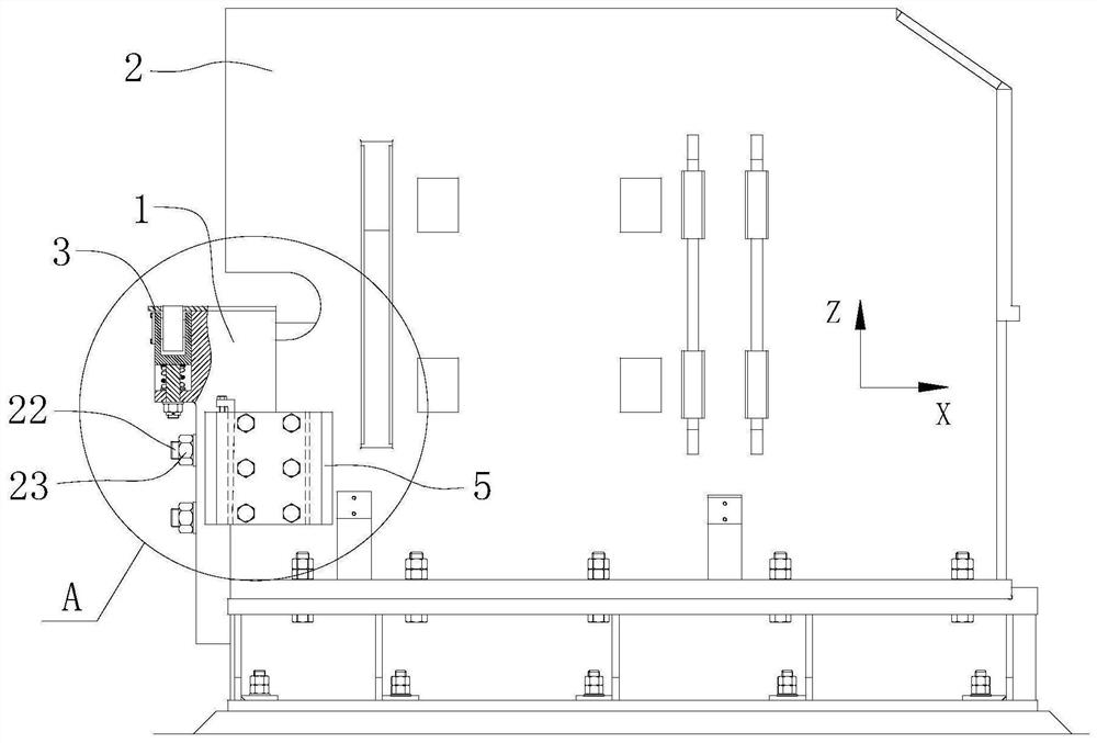
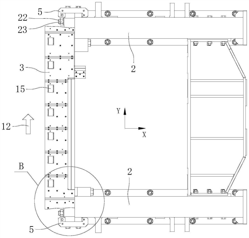
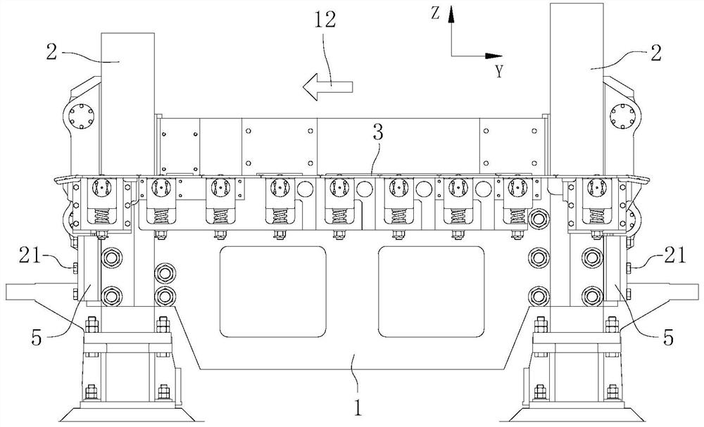
[0030] figure 1 It is a structural schematic diagram of the lower tool rest device provided by the embodiment of the present invention; figure 2 yes figure 1 top view of image 3 yes figure 1 left view of Figure 4 yes figure 1 Enlarged image at A. Figure 1 to Figure 4 Among them, X-direction, ...


PUM


Abstract

The invention relates to the technical field of shearing equipment, and provides a lower knife rest device, including a lower knife rest and a frame combined with the lower knife rest; the top of the lower knife rest is provided with a lower knife rest guard; A plurality of roller devices are arranged at intervals along the incoming material direction below the lower knife rest guard plate; the roller devices include mounting seats, roller frames, rollers and elastic reset members. By setting the roller device, the sheet material is supported and conveyed by the roller device during the sheet feeding process, which not only avoids the contact between the sheet material and the lower knife rest guard plate, but also solves the problem of serious wear of the lower knife rest guard plate in the prior art. Moreover, the rolling cooperation between the sheet material and the rollers in the roller device reduces the frictional force of the sheet material in the conveying process. During the shearing process, the shearing force makes the rollers of the roller device move downwards, and then the plate is carried by the lower knife rest guard plate, which avoids damage to the roller device due to the large shearing force.

Description

technical field [0001] The invention relates to the technical field of shearing equipment, in particular to a lower knife rest device. Background technique [0002] The top of the lower knife rest of the roll-cut double-sided shear is equipped with a lower knife rest guard. When feeding the plate, the sheet material slides and rubs on the lower knife rest guard. Every time the plate is fed, the lower knife rest guard will be worn. It will cause serious wear and tear of the lower knife rest guard, reducing the service life of the lower knife rest guard. [0003] The lower knife rest and the frame in the rolling-cut double-sided shear are connected together by studs, and because the size and joint position of the studs are limited by the structural space of the equipment, when the steel plate is cut, there will be studs. The phenomenon that the column is loose or elastically elongated will cause a gap between the joint surface between the lower tool holder and the frame, comm...

Claims


Application Information

Patent Timeline
Patent Type & Authority Patents(China)
IPC IPC(8): B23D33/00B23D33/02B23D35/00
CPCB23D35/002B23D33/00B23D33/02
Inventor 陈伦树
Owner CHINA ERZHONG GRP DEYANG HEAVY IND
Why Eureka
Try Eureka