Needle head of guide needle

A technology of guiding needles and needles, applied in the directions of guiding needles, catheters, etc., can solve the problems of difficulty in maintaining the sharpness of the needle tip, unfavorable wound suturing and healing, and large puncture resistance, so as to eliminate transverse cutting injuries, facilitate suturing and healing, The effect of reducing puncture resistance

Pending Publication Date: 2021-04-27
天津翔越医疗器械有限公司
View PDF0 Cites 1 Cited by
  • Summary
  • Abstract
  • Description
  • Claims
  • Application Information

AI Technical Summary

Problems solved by technology

[0003] ①The sharpness of the needle point is not easy to maintain: the needle point is generally protected by a hard soft plastic tube sleeve, the tip of the gun is close to the wall of the tube, and the strength of the tip of the gun is limited due to the material limitation. Increased puncture resistance and more tissue damage to patients during use;
[0004] ②The cutting edge of the needle tip adopts the transverse grinding process, the sharpness is poor, and the puncture resistance is large;
[0005] ③ Different puncture operation methods have different degrees of difficulty in operation and increased trauma to patients: Doctors generally have two puncture operation tendencies—forward piercing and upward piercing. When doctors use forward piercing, the damage to the tissue The wound is generally triangular (or T-shaped), which has great resistance to the forward movement of the needle, and the transverse cutting damage to the tissue (especially muscle) is obvious, and the wound on the skin surface is triangular (or T-shaped) after passing through. ) is very unfavorable to the suture and healing of the wound after the drainage tube is withdrawn; when the doctor uses upward piercing, the wound formed on the tissue is basically linear, and the horizontal cutting of the tissue is less harmful. The wound on the skin surface is linear, which is beneficial Suturing and healing in the later stage, but because the blade of the needle is generally relatively long, when picking through, the longitudinal cutting width of the tissue is often too wide, and even the wound on the skin is too long, resulting in air leakage and puncture failure

Method used


Image

  • Needle head of guide needle
  • Needle head of guide needle
  • Needle head of guide needle

Examples


Embodiment 1

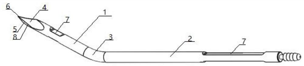
[0033] The present invention provides a guide needle needle head, comprising an inner cutting edge plane 4, one side of the inner cutting edge plane 4 is provided with an outer cutting edge plane 5, and the inner cutting edge plane 4 and the outer cutting edge plane 5 intersect at the needle tip 6 , the inner cutting edge plane 4 is asymmetrical to the outer cutting edge plane 5, that is, it is asymmetrical about the central axis of the needle 1, and the size of the outer cutting edge plane 5 is smaller than the size of the inner cutting edge plane 4, and the size is the cutting edge plane width and length; if the inner cutting edge plane 4 is completely symmetrical to the outer cutting edge plane 5, the cutting edge plane will be perpendicular to the plane where the puncture line is located, which will cause serious transverse damage to the tissue (especially muscle) during puncture Cutting, through the asymmetric setting, the plane of the cutting edge can be coplanar with the...

Embodiment 2

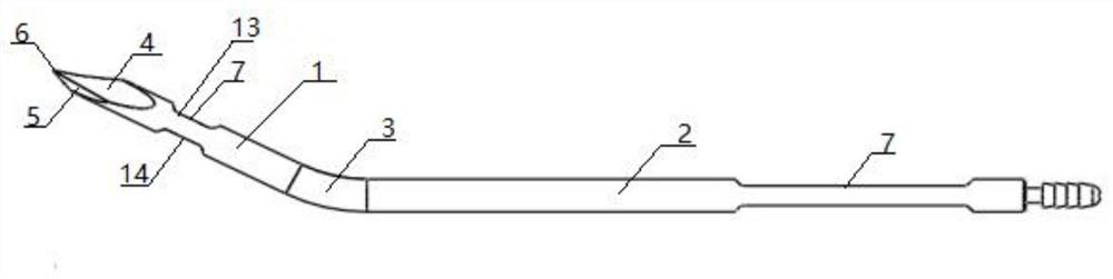
[0035] In this embodiment, the inner cutting edge plane 4 and the outer cutting edge plane 5 are specifically defined. Specifically, the inner cutting edge plane 4 includes a first inner cutting edge plane 9 and a second inner cutting edge plane 10. One side of an inner cutting edge plane 9 is provided with a second inner cutting edge plane 10, and the other side of the first inner cutting edge plane 9 is provided with a first outer cutting edge plane 11, and the first outer cutting edge plane One side of 11 is provided with a second outer cutting edge plane 12, one side of the second outer cutting edge plane 12 is provided with a second inner cutting edge plane 10, and one side of the second inner cutting edge plane 10 is provided with The first inner cutting edge plane 9; the intersection line between the first inner cutting edge plane 9 and the second inner cutting edge plane 10, the intersection between the first inner cutting edge plane 9 and the first outer cutting edge p...

Embodiment 3

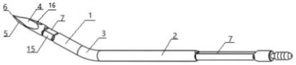
[0040] In this embodiment, a facet 16 is provided at the intersection line 8 between the inner cutting edge 4 and the outer cutting edge 5; more specifically, between the first inner cutting edge 9 and the first outer cutting edge 11 1. A facet 16 is provided at the intersection line 8 between the second inner cutting edge 10 and the second outer cutting edge 12; the length of the cutting edge is further reduced, and the width of the tissue longitudinally cut during operation is further reduced.


PUM


Abstract

The invention relates to the technical field of medical equipment, and provides a needle head of a guide needle. The needle head comprises an inner side cutting edge plane, wherein an outer side cutting edge plane is arranged on one side of the inner side cutting edge plane, the inner side cutting edge plane and the outer side cutting edge plane are asymmetric, and the size of the outer side cutting edge plane is smaller than that of the inner side cutting edge plane. A needle tip is designed into a spear tip shape from a current common prism shape, and cutting edge grinding lines are formed in the advancing direction of the needle. Compared with a traditional prism structure, for the needle head disclosed by the invention, puncture resistance can be effectively reduced, transverse cutting damage of a traditional needle head to tissue is eliminated, and suturing and healing of a puncture hole are facilitated. A set of grinding planes and an outer side cutting edge are additionally arranged on the outer side of the needle tip, the width of a newly-added outer side cutting edge plane grinding surface is smaller than that of the inner side cutting edge plane, and the length of the newly-added outer side cutting edge plane grinding surface is smaller than that of the inner side cutting edge plane, so that the front end of the needle tip is in a spear tip shape but asymmetric, and the overall length of the needle tip is shortened. The needle tip does not abut against the wall of a sheath, and damage to the needle tip in the storage and transportation process is basically eliminated.

Description

technical field [0001] The invention relates to the technical field of medical equipment, in particular to a guide needle needle. Background technique [0002] Drainage tubes play a very important role in surgical operations. During postoperative catheter drainage treatment, one end of the catheter is generally implanted in the body, and the other end is exposed outside the body for drainage; the drainage tube needs to be passed through a drainage guide needle. Therefore, the drainage guide needle is also an indispensable part of the surgical operation; the drainage guide needle is composed of a needle handle and a needle head, and the needle head is the most important part of the guide needle, which determines whether the catheter can be installed smoothly, and determines the patient Whether the wound is easier to heal; the introducer needle needle in the prior art mainly has the following defects: [0003] ①The sharpness of the needle point is not easy to maintain: the ne...

Claims


Application Information

Patent Timeline
IPC IPC(8): A61M25/06
CPCA61M25/0612A61M25/0618A61M25/065
Inventor 王海峰
Owner 天津翔越医疗器械有限公司
Why Eureka
Try Eureka