
Active matrix display and driving method thereof

An active matrix and display technology, applied in the field of display devices, can solve problems such as difficult to obtain high-speed operation, and achieve the effect of low price

Inactive Publication Date: 2003-11-05
SEMICON ENERGY LAB CO LTD
View PDF4 Cites 0 Cited by
  • Summary
  • Abstract
  • Description
  • Claims
  • Application Information

AI Technical Summary

Problems solved by technology

As a result, it is difficult to achieve high-speed operation

Method used

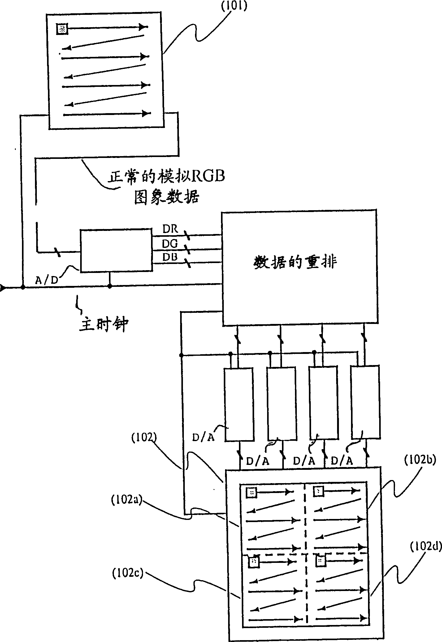
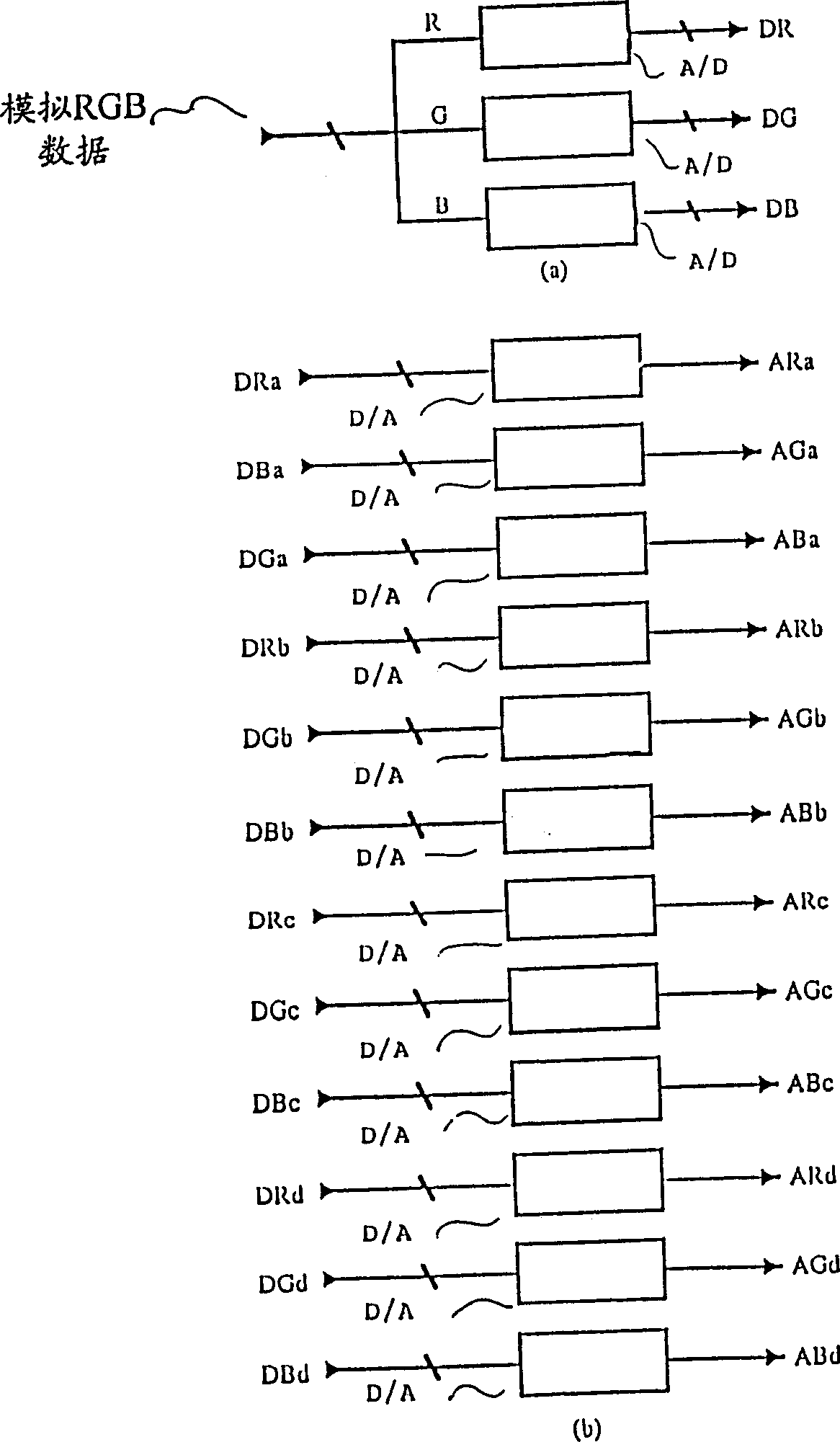
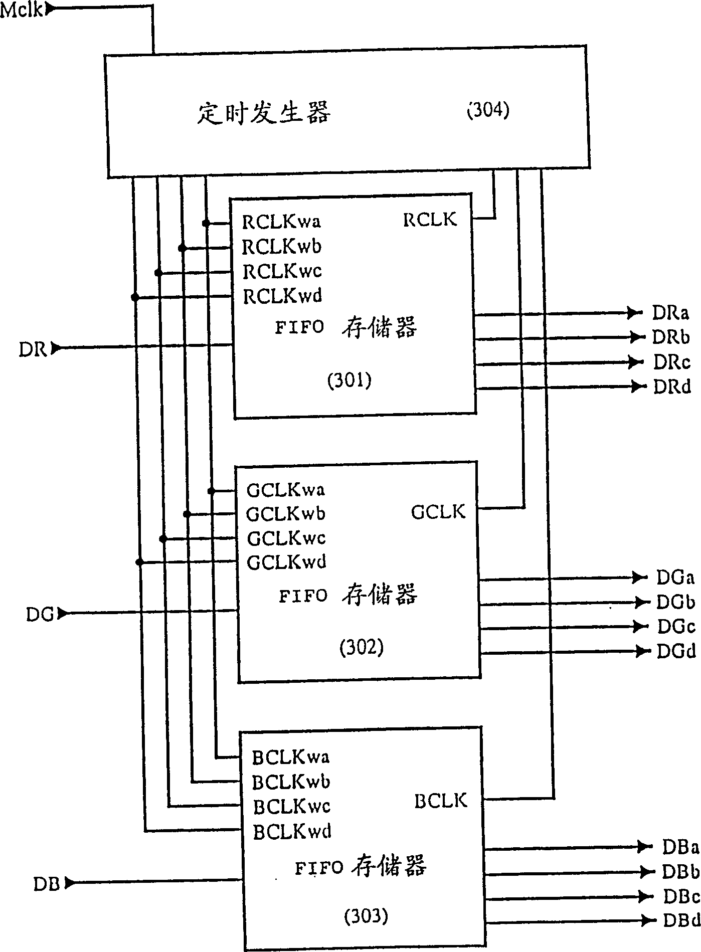

Image

  • Active matrix display and driving method thereof
  • Active matrix display and driving method thereof
  • Active matrix display and driving method thereof

Examples


example 3

[0083] Example 3 is similar to Example 2 except for the multilayer metallization structure. That is, the source side driver, gate side driver and part of the active matrix in Example 2 are the same as their corresponding parts in Example 3.

[0084] In Example 2, the source signal lines of source side drivers 1, 3 and 5 for each vertical line are twice as many as the source signal lines of source side driver circuits 2, 4 and 6, thus, if the signal lines in the pixel matrix and the signal lines in the sampling circuit are simply Figure 13 and the gate interconnections and aluminum interconnections shown in 14, the aperture ratios of pixel matrices 1, 3 and 14 deteriorate.

[0085] in the use of such as Figure 16 and 17 In the case of the multilayer metallization structure shown, even when multiple driver circuits are used, the operating rate can be improved without sacrificing the aperture ratio.

[0086] exist Figure 16 , the laminated aluminum interconnects 1 and 2 f...


PUM


Abstract

A display for a matrix display, which provides at least a first part and a second part separate from the first part, a display part comprising at least a first display area and a second display area, each display area comprising a an active matrix circuit of a plurality of pixel electrodes and a plurality of switching elements for switching the pixel electrodes, wherein the first display area is formed on the first part, and the second display area is formed on the On the second part; first and second signal line driver circuits for respectively supplying image signals to the active matrix circuits of said first and second display areas; and first and second scan line driver circuits for The active matrix circuit for scanning the first display area and the second display area respectively; wherein the first and second signal line driver circuits are respectively located outside the display part, and they make the first and second display The active matrix circuits in the regions are scanned or driven in opposite directions to each other.

Description

technical field [0001] BACKGROUND OF THE INVENTION Field of the Invention The present invention relates to a display device suitable for displaying high-quality images (such as HDTV) using high-speed, large-volume image data, and more particularly, to an electro-optic liquid crystal display. The present invention also relates to a driving method of the above-mentioned display device. Background technique [0002] Figure 20 Shown is a block diagram of a prior art system for providing an image display. Such a system has an image reader 2001, such as a video camera. Such an image reader scans a desired image (still image or moving image) and generates output data. A display device 2002, such as an electro-optic liquid crystal display, under the control of a controller unit connected between the display device 2002 and the image reader 2001, uses the output data from the image reader 2001, that is, provides a show. [0003] next reference Figure 21 An electro-optical acti...

Claims


Application Information

Patent Timeline
Patent Type & Authority Patents(China)
IPC IPC(8): G02F1/136G02F1/133G02F1/1368G09G3/36H04N5/66
CPCG09G3/3655G09G3/3666G09G3/3677G09G3/3688G09G2310/0297G09G2352/00G02F1/133
Inventor 山崎舜平小山润千村秀彦
Owner SEMICON ENERGY LAB CO LTD
Learn More