
Rapid drilling system and drilling process for concrete deep crack detection

A technology for deep cracks and concrete, which is applied in the field of rapid drilling system and drilling technology for deep crack detection in concrete. It can solve problems such as harmful health, large dust, and inability to adjust the angle of the drill bit, and achieve the effect of preventing jamming

Inactive Publication Date: 2021-04-23
叶双春
View PDF0 Cites 2 Cited by
  • Summary
  • Abstract
  • Description
  • Claims
  • Application Information

AI Technical Summary

Problems solved by technology

[0003] Only by using the detection method to find out the cracks can the next step of filling the cracks be carried out. During the detection process, a drilling device is needed, but the existing drilling devices have the following defects: 1. It is not easy to move and difficult to carry; 2. There will be a lot of dust during the drilling process, and the long-term inhalation of dust by construction workers is harmful to health; 3. It is difficult to collect the dust during drilling; 4. The angle of the drill bit cannot be adjusted during drilling, and the depth of the drilling cannot be controlled. We propose a rapid drilling system and drilling process for detecting deep cracks in concrete to solve the above-mentioned problems

Method used


Image

  • Rapid drilling system and drilling process for concrete deep crack detection
  • Rapid drilling system and drilling process for concrete deep crack detection
  • Rapid drilling system and drilling process for concrete deep crack detection

Examples


Embodiment 1

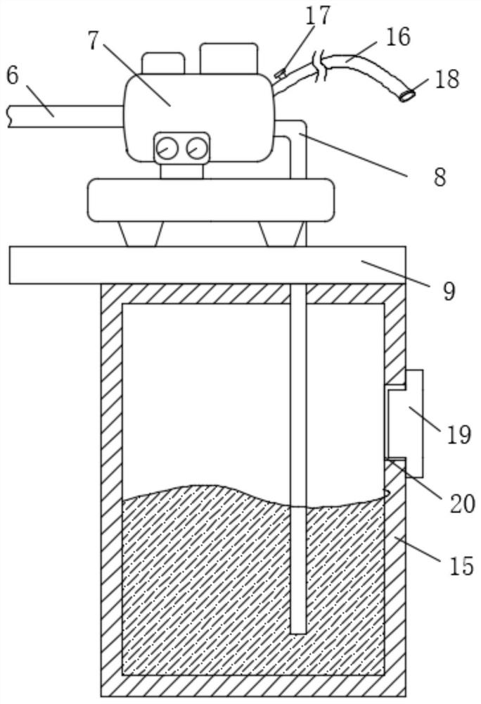
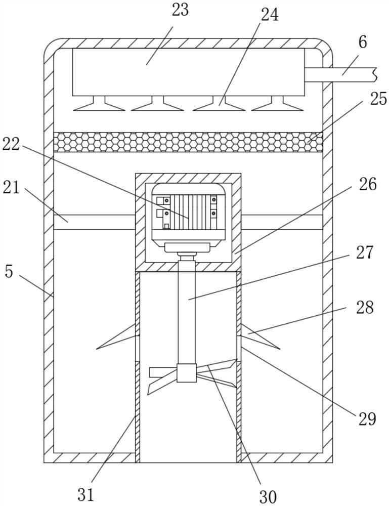
[0047] Embodiment one: if Figure 1-3 , 5-15, a rapid drilling system for detecting deep cracks in concrete, including a base plate 3, the top of the base plate 3 is fixedly connected with a rectangular box 4, a dust collection box 5 and a water tank 15, and the bottom of the base plate 3 is fixedly connected with two Two symmetrical four support blocks 14, the inside of the two support blocks 14 on the same side are connected to the same rotating shaft 2, the two ends of the rotating shaft 2 are fixedly connected to the wheels 1, and the bottom of the base plate 3 is provided with a ring for preventing dust from getting out. The inside of the rectangular box 4 is provided with an adjustment assembly for adjusting the drilling angle, the inside of the rectangular box 4 is provided with a drilling assembly for drilling, and the bottom inner wall of the dust collection box 5 is fixedly connected with a suction device for dust collection. Dust assembly, the inside of the water ta...

Embodiment 2

[0063] Embodiment two: if Figure 4As shown, a rapid drilling system for detecting deep cracks in concrete. The difference between this embodiment and Embodiment 1 is that: one side of the rectangular box 4 is fixedly connected with two symmetrically arranged hinges 32, and one side of the two hinges 32 The same box door 33 is fixedly connected, and the same door lock 34 is fixedly connected to one side of the box door 33 and the rectangular box 4 .

[0064] Working principle: open the door lock 34 by hand, turn the box door 33 to open the box door 33, unscrew the first screw 42 from the thread groove 38, turn the hand wheel 44, the hand wheel 44 drives the fixed box 41 to rotate, and the fixed box 41 Drive the mounting plate 43 to rotate. When rotating to a suitable angle, screw the first screw rod 42 into the threaded groove 38 to fix the fixed box 41. Rotate the second screw rod 45 by hand, and the second screw rod 45 will lift in the vertical direction Movement, the secon...


PUM


Abstract

A rapid drilling system for concrete deep crack detection is disclosed in the invention, and comprises a bottom plate, the top of the bottom plate is fixedly connected with a rectangular box, a dust collecting box and a water tank, the bottom of the bottom plate is fixedly connected with four supporting blocks which are symmetrical in pairs, and the interiors of the two supporting blocks located on the same side are rotationally connected with the same rotating shaft; wheels are fixedly connected to the two ends of the rotating shaft, a protection assembly used for preventing dust from leaking outwards is arranged at the bottom of the bottom plate, and an adjusting assembly used for adjusting the drilling angle is arranged in the rectangular box. The invention further discloses a drilling process. The system is simple in structure, movement of the device can be achieved through wheels, movement of the device is more convenient, the angle of a drill bit is adjusted through an adjusting assembly, the punching depth is controlled by rotating a second screw rod, and then a protection assembly is used for preventing dust from leaking to harm the body health of construction personnel; and dust is collected through a dust collection assembly and a dust falling assembly, and operation is easy.

Description

technical field [0001] The invention relates to the technical field of concrete crack detection, in particular to a rapid drilling system and a drilling process for detecting deep concrete cracks. Background technique [0002] Concrete cracks are the physical structure changes of concrete structures due to the action of internal and external factors, and cracks are the main reason for the reduction of the bearing capacity, durability and water resistance of concrete structures. The common treatment methods for concrete cracks include filling method, grouting method, structural Reinforcement method, concrete replacement method, electrochemical protection method, etc. [0003] Only by using the detection method to find out the cracks can the next step of filling the cracks be carried out. During the detection process, a drilling device is needed, but the existing drilling devices have the following defects: 1. It is not easy to move and difficult to carry; 2. There will be a ...

Claims


Application Information

Patent Timeline
Patent Type & Authority Applications(China)
IPC IPC(8): G01N33/38
CPCG01N33/38
Inventor 叶双春熊立
Owner 叶双春
Learn More